Eddy current testing probe and eddy current testing apparatus

a testing probe and eddy current technology, applied in the direction of instruments, magnetic measurements, measurement devices, etc., can solve the problem that the detection of faults cannot be performed correctly

Active Publication Date: 2006-08-03
HITACHI LTD
View PDF7 Cites 30 Cited by
  • Summary
  • Abstract
  • Description
  • Claims
  • Application Information

AI Technical Summary

Benefits of technology

[0008] In the above eddy current testing probe, since a deformation of the elastic member caused by the pressing member is limited by the movement limiting member, the coils are prevented from being deformed by the pressing member through the elastic member so that a flaw detection can be performed correctly without the deformation of the coils.
[0009] As explained above, the eddy current testing probe and eddy current testing apparatus in which the flaw detection can be performed correctly without the deformation of the coils are obtainable.

Problems solved by technology

If the coils are deformed by the pressing force, the eddy current of designed value cannot be applied correctly to the test article and the generated eddy current cannot be measured correctly so that the flaw detection cannot be performed correctly.

Method used


Image

  • Eddy current testing probe and eddy current testing apparatus
  • Eddy current testing probe and eddy current testing apparatus
  • Eddy current testing probe and eddy current testing apparatus

Examples


first embodiment

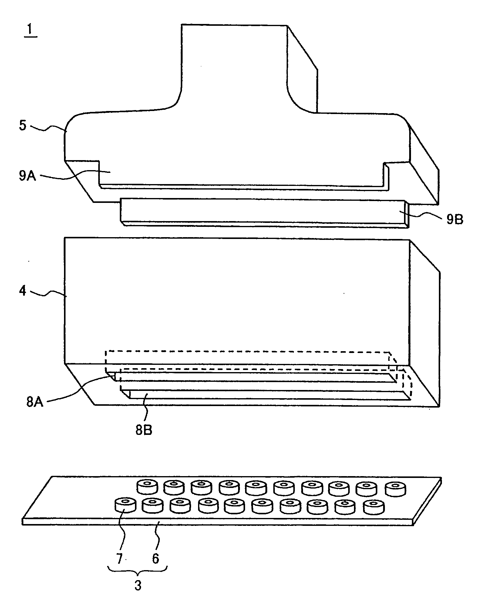
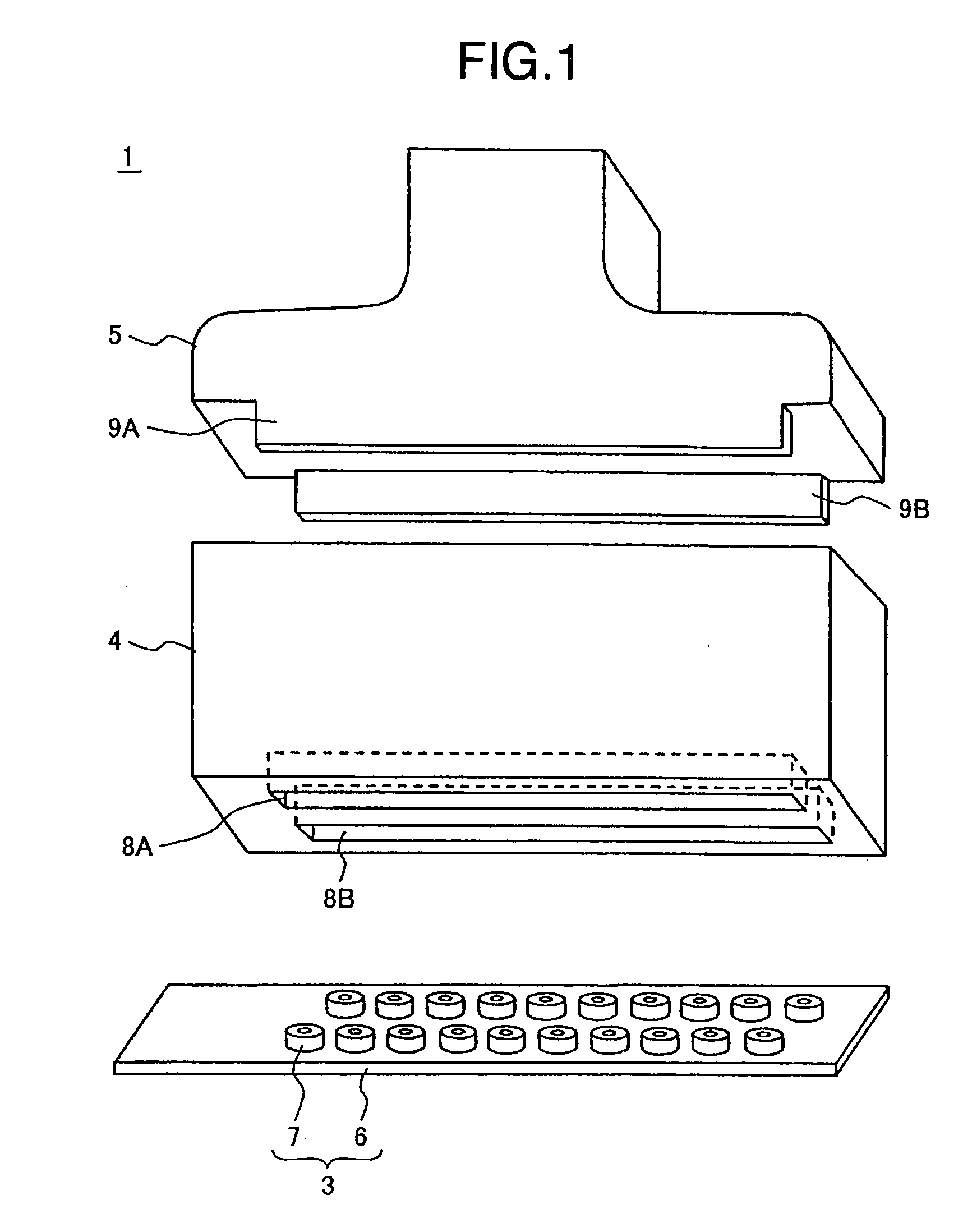
[0023] Hereafter, eddy current testing probe of the invention is explained on the basis of FIGS. 1 and 2.

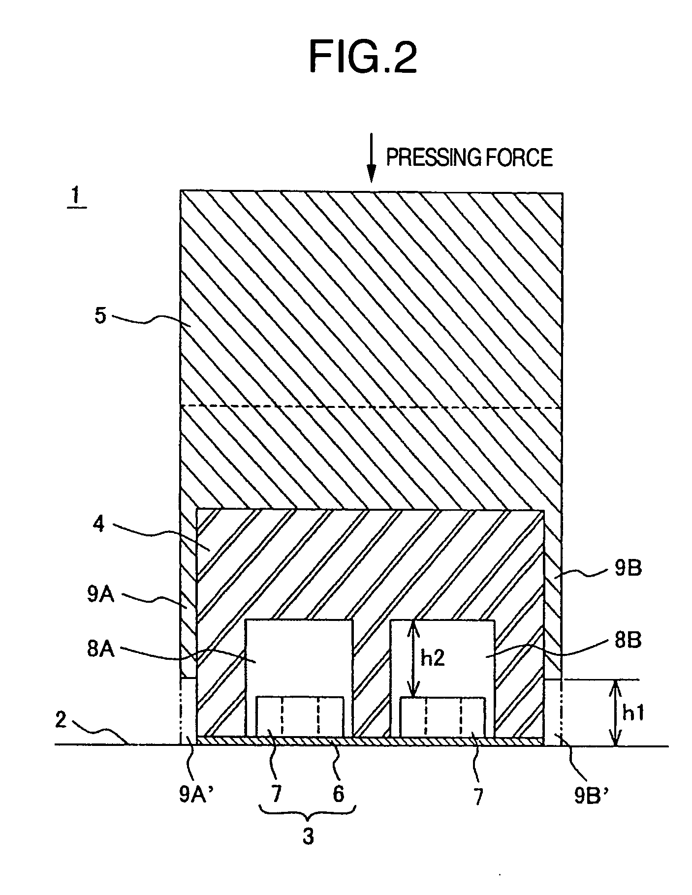
[0024] An eddy current testing probe 1 includes a flaw detection sensor 3 for facing to a surface of a test article 2, an elastic member 4 for pressing the flaw detection sensor 3 against the test article 2, and a pressing member 5 for pressing the elastic member 4 so that the flaw detection sensor 3 is pressed against the test article 2.

[0025] The flaw detection sensor 3 includes a flexible substrate 6 including a stack of films of, for example, polyimide, and a plurality of coils 7 fixed along single direction to the flexible substrate 6 through an adhesive or the like having flexibility after being cured in such a manner that the flexible substrate 6 is arranged between the coils 7 and the test article 2. In this embodiment, the coils 7 form two rows, and electric wires (not shown) connected to the coils 7 respectively extend between the polyimide films in the stack.

[0026] T...

fourth embodiment

[0039] The eddy current testing probe 1C as the invention as shown in FIGS. 5 and 6 solves these problems. In the eddy current testing probe 1C, the flaw detection sensor 3 of the same structure as the above embodiments is mounted on the elastic member 4 as the rectangular sponge of polyurethane or the like in such a manner that the flaw detection sensor 3 is arranged between the elastic member 4 and the test article 2, and a flexible thin plate 10 of stainless steel or the like having thickness of, for example, 0.1 mm is attached to the elastic member 4 in such a manner that the flexible thin plate 10 is arranged between the elastic member 4 and the pressing member 5. Bolts 11 are fixed to a surface of the flexible thin plate 10 opposite to the elastic member 4. On the other hand, the pressing member 5 has bolt holes 12 through which the bolts 11 extend so that the combined flexible thin plate 10, elastic member 4 and flaw detection sensor 3 are fixed by screwing nuts 13 onto the b...

fifth embodiment

[0042] When the test article 2 has the concave surface, as shown in FIG. 7 of the invention, the elastic member 4 and flaw detection sensor 3 are mounted through the flexible thin plate 10 onto the pressing member 5A as a substitute for the pressing member 5, which pressing member 5A has a convex shape on a surface thereof facing to the elastic member 4. By this attaching manner to the pressing member 5A, the flexible thin plate 10 is curved along the convex surface of the pressing member 5A, so that the elastic member 4 and flaw detection sensor 3 combined with the flexible thin plate 10 are curved to form the eddy current testing probe 1D corresponding to the concave surface of the test article 2.


PUM


Abstract

An eddy current testing probe has a flexible substrate adapted to face to a surface of a test article, a plurality of coils which are fixed to the flexible substrate and energized one of which is capable of being changed sequentially, a pressing member for pressing the substrate toward the test article, an elastic member arranged between the substrate and the pressing member, and a movement limiting member for limiting a movement of the pressing member toward the test article.

Description

BACKGROUND OF THE INVENTION [0001] The present invention relates to an eddy current testing probe and eddy current testing apparatus, particularly to an eddy current testing probe and eddy current testing apparatus for detecting a flaw in a test article by changing sequentially energized one(s) of a plurality of coils to detect a flaw signal generated by a detecting coil. [0002] The eddy current testing probe and eddy current testing apparatus for detecting the flaw in the test article by changing sequentially energized one(s) of the plurality of coils to detect the flaw signal generated by the detecting coil, was already provided as shown by, for example, JP-A-2003-344360. [0003] That is, in these, the plurality of coils are arranged on a flexible substrate so that the coils are pressed against a surface of the test article by an elasticity such as a leaf spring or the like, and under this situation, energized one(s) of the coils is sequentially changed to detect the flaw in the te...

Claims


Application Information

Patent Timeline
Patent Type & Authority Applications(United States)
IPC IPC(8): G01R33/12
CPCG01N27/9013G01N27/904
Inventor NISHIMIZU, AKIRAMATSUI, TETSUYAKOIKE, MASAHIRONONAKA, YOSHIOYOSHIDA, ISAO
Owner HITACHI LTD
Why Eureka
Try Eureka