Method and apparatus for initializing a delay locked loop

Active Publication Date: 2006-08-03
CONVERSANT INTPROP MANAGEMENT INC
View PDF31 Cites 43 Cited by
  • Summary
  • Abstract
  • Description
  • Claims
  • Application Information

AI Technical Summary

Benefits of technology

[0015] In the known art, solutions to ensure steady lock and good performance of a DLL include complicated structures such as dual-loop structures. Multiphase versions of the clock signal or clock inversion in the simplest case are also used. However they are used in order to minimi

Problems solved by technology

The phase taps in turn are used to increase flexibility in synchronization of pipeline stages, but not for the purposes of achieving steady lock a

Method used


Image

  • Method and apparatus for initializing a delay locked loop
  • Method and apparatus for initializing a delay locked loop
  • Method and apparatus for initializing a delay locked loop

Examples


Embodiment Construction

[0039] A description of preferred embodiments of the invention follows.

[0040] In the following description, numerous specific details are set forth to provide a thorough understanding of the invention. However, it is understood that the invention may be practised without these specific details. In other instances, well-known structures or and / or processes have not been described or shown in detail in order not to obscure the invention. In the description and drawings, like numerals refer to like structures or processes. Generally, operation of a Delay Locked Loop (DLL) is well known in the art and will not be described further except where necessary to clarify aspects of the invention.

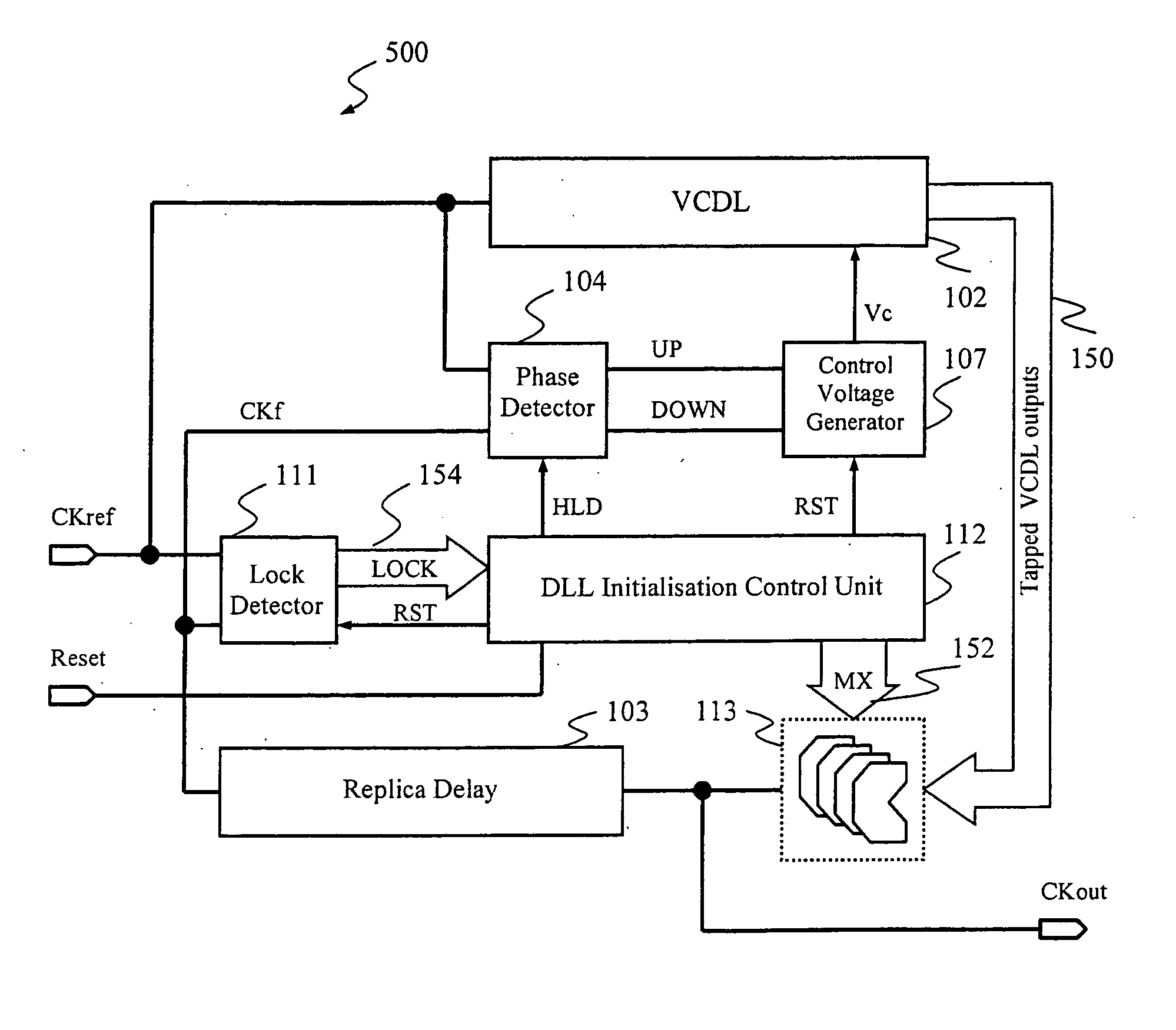
[0041]FIG. 5 is a block diagram of an embodiment of a Delay Lock Loop (DLL) 500 that includes a DLL Initialization control 112 for initializing the DLL 500 after power-up or reset according to the principles of the present invention. The DLL 500 includes a Voltage Controlled Delay Line (VCDL) 102, Ph...


PUM


Abstract

A delay locked loop includes initialization circuitry that ensures that a DLL is initialized to an operating point that is not to close to either end of a delay vs. control voltage characteristic. The initialization circuitry forces the DLL to initially search for a lock point starting from an initial delay, the delay is varied in one direction, forcing the DLL to skip the first lock point. The initialization circuitry only allows the DLL to vary the delay of the voltage controlled delay loop in the one direction from the initial delay until the operating point is reached.

Description

BACKGROUND OF THE INVENTION [0001]FIG. 1 is a block diagram of a prior art conventional Delay Locked Loop (DLL) 100. The main function of a DLL is to synchronize two clock signals by aligning their rising edges. An externally supplied clock signal CK is buffered by clock buffer 101 to provide a reference clock signal CKref that is coupled to a voltage controlled delay line (VCDL) 102 and a phase detector (PD) 104. The voltage controlled delay line 102 produces a DLL output clock signal CKout, which is a delayed version of CKref and is routed to various circuits within a device through a buffering structure referred to as a clock tree. [0002] A feedback clock signal CKf is tapped at a terminal node of a branch of the clock tree or obtained by applying the output clock signal CKout to a replica of the clock tree branch, that is, a replica delay circuit 103 and fed back to the PD 104. The replica delay circuit 103 also known as a delay model or a clock tree branch replica, reproduces a...

Claims


Application Information

Patent Timeline
IPC IPC(8): H03L7/06
CPCH03L7/0812H03L7/0891H03L7/08H03L7/095H03L7/10H03L7/0895H03L7/0816H03L7/06
Inventor HAERLE, DIETERMAI, TONYVLASENKO, PETER
Owner CONVERSANT INTPROP MANAGEMENT INC
Why Eureka
Try Eureka