Wireless point multipoint system

a multi-point system and wireless technology, applied in the field of wireless point to multi-point systems, can solve problems such as inefficient use of tables

Inactive Publication Date: 2006-08-03
TRANGO NETWORKS LLC
View PDF16 Cites 72 Cited by
  • Summary
  • Abstract
  • Description
  • Claims
  • Application Information

AI Technical Summary

Problems solved by technology

Accordingly, such tables are limited in the number of user devices that can be associated with any given subscriber unit and become inefficient in use of the table as the number of entries increases.

Method used


Image

  • Wireless point multipoint system
  • Wireless point multipoint system
  • Wireless point multipoint system

Examples


Embodiment Construction

[0038] Reference will now be made in detail to presently preferred embodiments of the invention, one or more examples of which are illustrated in the accompanying drawings. Each example is provided by way of explanation of the invention, not limitation of the invention. In fact, it will be apparent to those skilled in the art that modifications and variations can be made in the present invention without departing from the scope or spirit thereof. For instance, features illustrated or described as part of one embodiment may be used on another embodiment to yield a still further embodiment. Thus, it is intended that the present invention covers such modifications and variations as come within the scope of the appended claims and their equivalents.

[0039] A. System Configuration

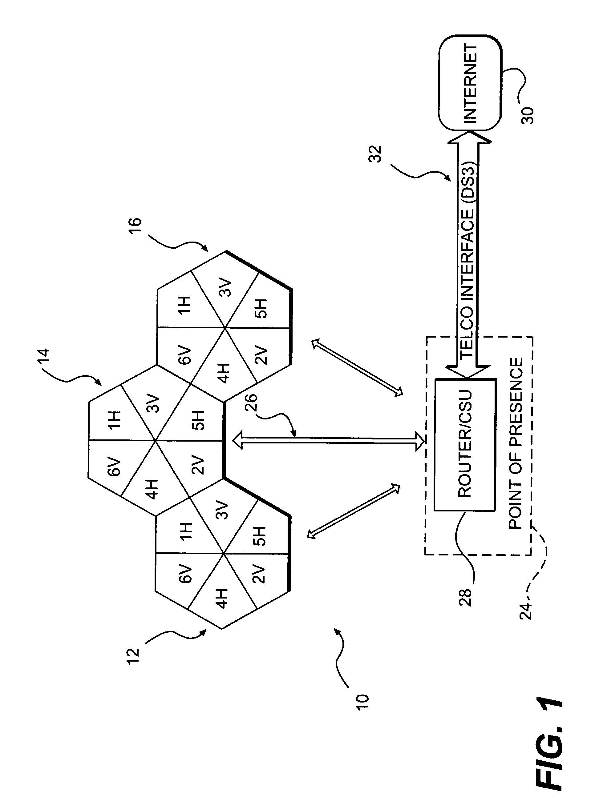
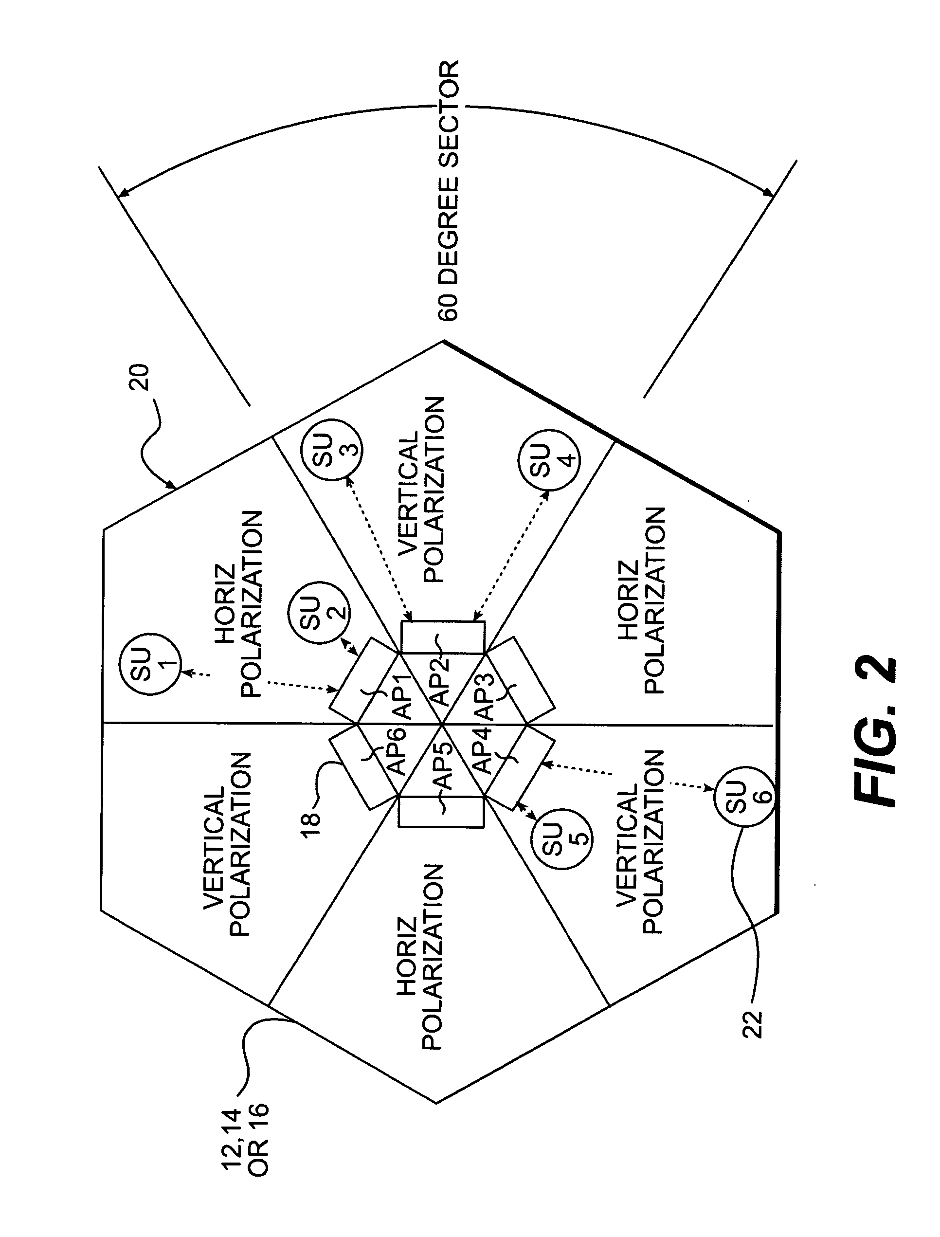
[0040] An exemplary deployment of a point to multipoint fixed wireless network system 10 comprised of three base station cells is shown in FIG. 1. Each base station cell 12, 14 and 16 is divided into sixty degr...


PUM


Abstract

A patch array antenna includes a planar base on which is defined a ground plane and feed positions that are electrically isolated from the ground plane. A plurality of patch elements are configured to resonate over a predetermined frequency range. Each patch element is isolated from the ground plane and disposed on the base over the ground plane so that an air dielectric is defined between the patch element and the ground plane. Each patch element defines a resonant portion that is electrically connected to a respective feed position. A feed network is defined on the base that electrically connects the feed positions to one or more output points on the base.

Description

[0001] This is a division of U.S. application Ser. No. 10 / 264,983, filed Oct. 4, 2002, which is a continuation-in-part of U.S. application Ser. No. 10 / 263,210, filed Oct. 1, 2002, now abandoned, entitled “Wireless Point to Multipoint System,” the entire disclosures of which are incorporated by reference herein.BACKGROUND OF THE INVENTION [0002] The present invention relates to wireless point to multipoint systems. Systems are known in which a base station transmits electromagnetic signals to, and receives electromagnetic signals from, subscriber units within a sector allocated to the base station. User devices are attached to each subscriber unit, and the base station forwards data to the user devices through their corresponding subscriber units as the data is received by the base station from an outside source, for example the Internet. In one type of known system, the base station designates certain time periods, called “contention periods,” in which the subscriber units are eligi...

Claims


Application Information

Patent Timeline
Patent Type & Authority Applications(United States)
IPC IPC(8): H01Q1/38H01Q21/00H01Q1/22H01Q1/24H01Q21/06H01Q25/00H04B7/26H04L12/28H04L12/56H04W4/06H04W72/04H04W88/08
CPCH01Q1/2258H01Q21/0075H01Q21/065H01Q25/001H04W4/06H04W72/0453H04W88/08
Inventor GUSTAF, CHRISTOPHER A.
Owner TRANGO NETWORKS LLC
Why Eureka
Try Eureka