Recording head driving device and printing apparatus

Inactive Publication Date: 2006-08-03
FUJIFILM BUSINESS INNOVATION CORP
View PDF0 Cites 10 Cited by
  • Summary
  • Abstract
  • Description
  • Claims
  • Application Information

AI Technical Summary

Benefits of technology

[0014] The present invention has been devised in consideration of the problems described above, and will provide a recording head driving device and printing apparatus with small size and good energy efficiency, in which waveforms of driving signals are preserved.

Problems solved by technology

Consequently, in a conventional printing apparatus, because a capacitance value of the load varies with the number of the droplet ejectors that are ejecting ink drops (i.e., printing density), waveforms of driving signals are disturbed, and problems arise in that sizes of ink drops vary and so forth.
However, with this kind of capacitive load driving circuit, it is necessary to supply energy to the dummy loads even when the number of actuating elements to be driven (i.e. the loading capacitance of the actuating elements) is small.
As a result, power is consumed excessively.
Particularly in recent years, there has been a trend in which the number of droplet ejectors that are provided at heads are increased, in order to realize high-speed printing, and overall power consumption of heads has been increasing.
In such a case, because power efficiency of the amplification circuit is low, power consumption amounts are greatly increased.
In addition, there is a problem in that heat generation amounts are accordingly increased, so larger radiator plates are necessary, and the device is increased in size.
However, there are range limitations with simple circuits, and it is difficult to adapt to this requirement.
Consequently, a problem arises in that the driving device is increased in size.
Further, with an inkjet driving device which is provided with current amplification sections covering a plurality of heads, problems also arise in that distribution of wiring is more complicated and terminals connecting the respective current amplification sections to the respective heads are required, which increases the size of the driving device.

Method used


Image

  • Recording head driving device and printing apparatus
  • Recording head driving device and printing apparatus
  • Recording head driving device and printing apparatus

Examples


Embodiment Construction

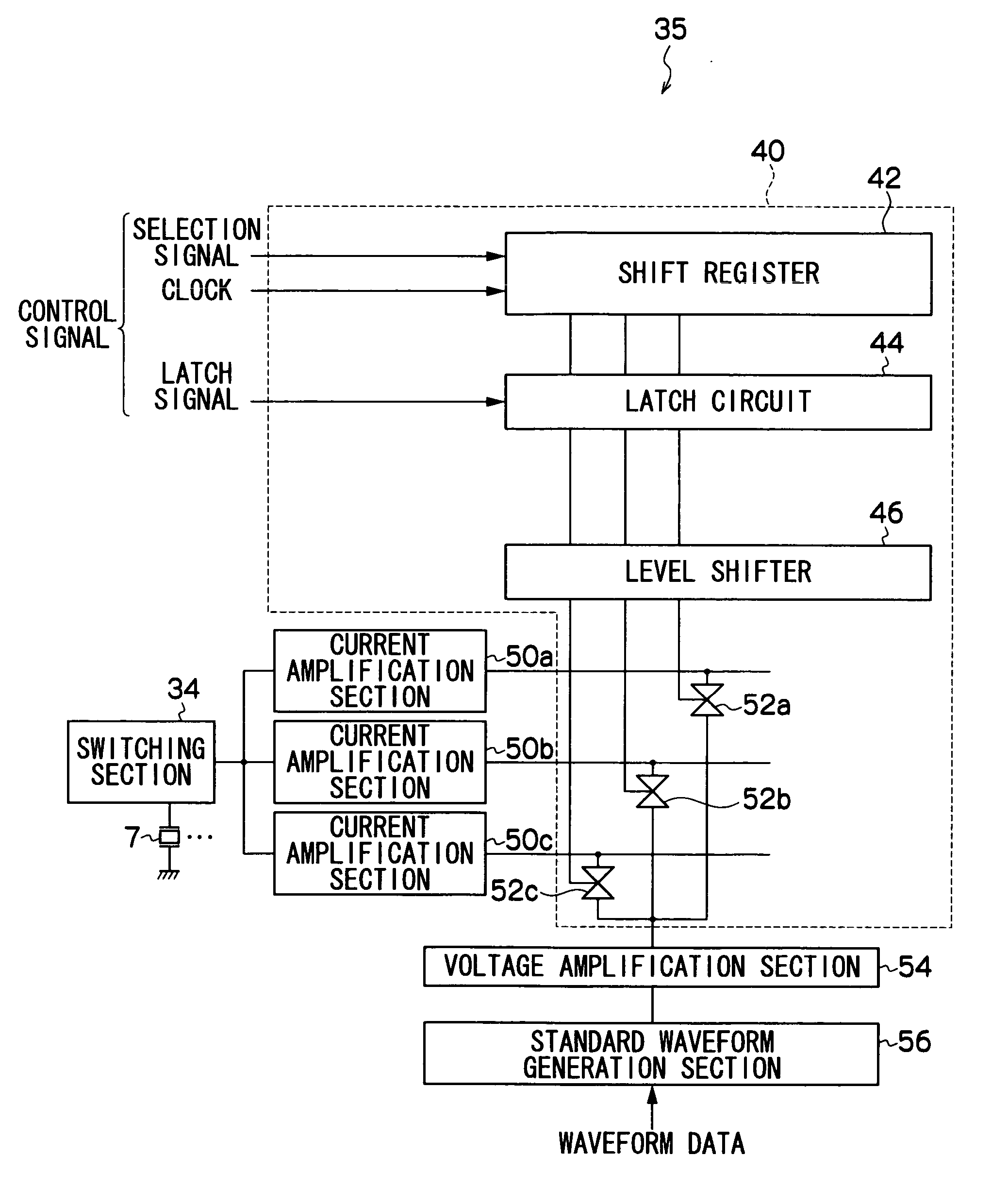
[0031] Herebelow, an embodiment of the present invention will be described in detail with reference to the drawings. A printing apparatus of the present embodiment is equipped with a recording head and a driving device.

[0032] The recording head driving device thereof drives the recording head, at which droplet ejection portions including actuating elements are plurally arranged, the actuating elements being driven such that droplets are ejected in accordance with driving signals.

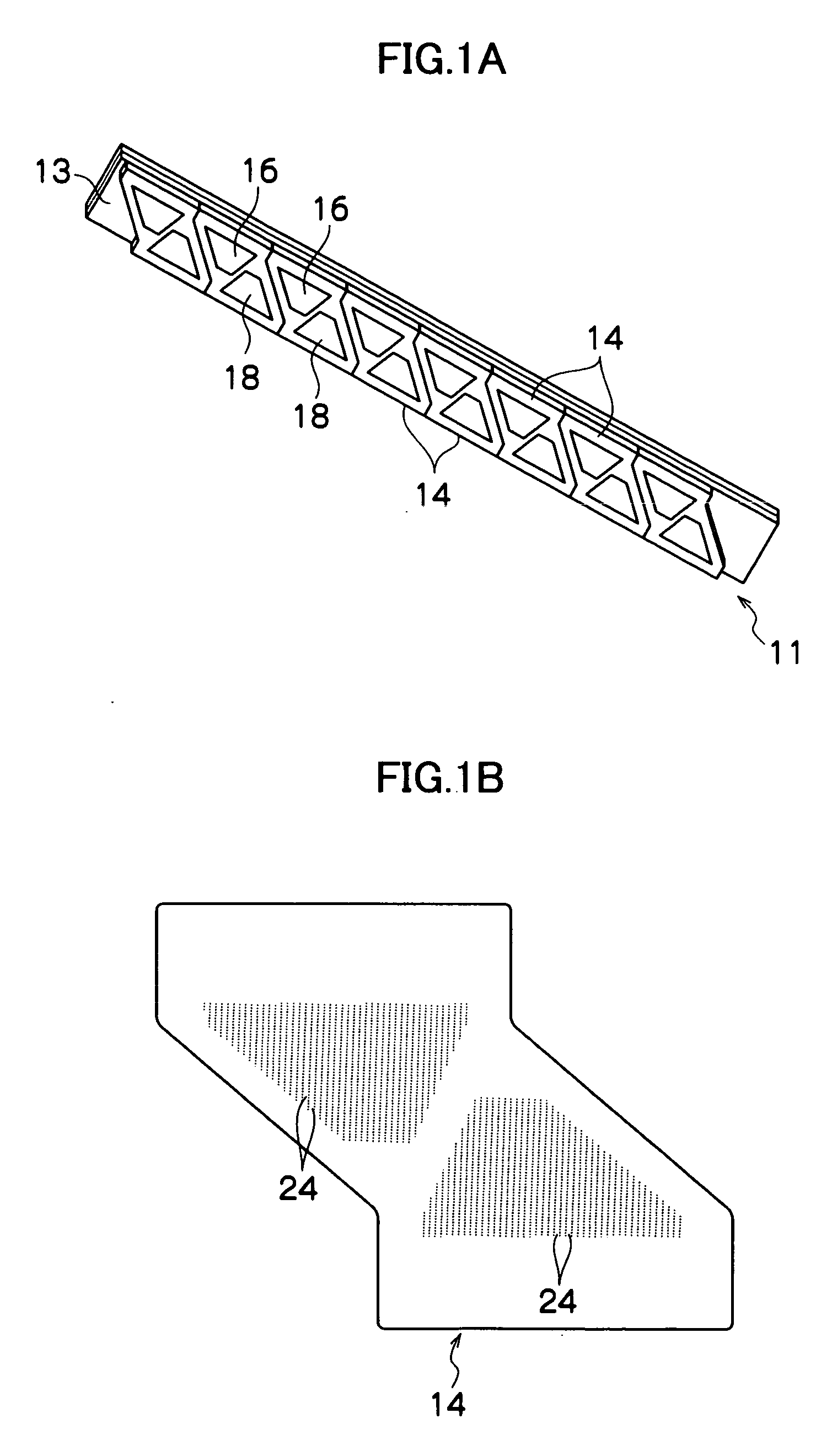
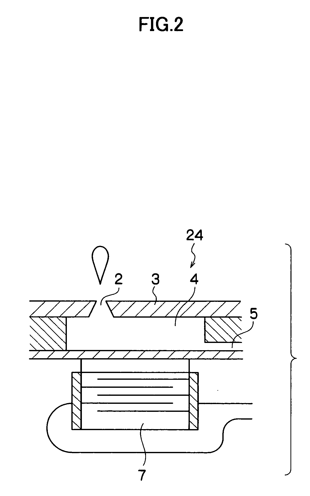
[0033]FIG. 1A is a schematic perspective view of a recording head 11 which is provided at the printing apparatus of the present embodiment, and FIG. 1B is a plan view of a head unit 14 which structures the recording head 11. As shown in FIG. 1A, the recording head 11 is equipped with a head bar 13, which is specified with a length corresponding to a maximum width of a recording medium. At this head bar 13, a plurality of the head unit 14 are joined together in a row and arranged in two dimensions. As shown...


PUM


Abstract

A driving device drives a recording head in which droplet ejection portions are plurally arrayed. The droplet ejection portions include actuating elements which are driven in accordance with driving signals such that droplets are ejected. The driving device is provided with a standard waveform generation section, a voltage amplification section, a plurality of current amplification sections and a selection section. Output terminals of the current amplification sections are commonly connected. The selection section selects at least one of the plurality of current amplification sections, in accordance with the number of the actuating elements to be driven concurrently or a printing density of an image to be printed by the recording head. The selection section inputs a driving signal, whose voltage component has been amplified by the voltage amplification section, to input terminal(s) of the selected current amplification section(s).

Description

CROSS-REFERENCE TO RELATED APPLICATION [0001] This application claims benefit of and priority to Japanese Patent Application No. 2005-026170, filed on Feb. 2, 2005, which is incorporated herein by reference in its entirety for all purposes. BACKGROUND OF THE INVENTION [0002] 1. Field of the Invention [0003] The present invention relates to a driving device for a recording head at which droplet ejection portions, which are equipped with actuating elements such that droplets are ejected in accordance with driving signals, are plurally arranged, and to a printing apparatus which includes this recording head. [0004] 2. Description of the Related Art [0005] As a recording head which is employed in an inkjet-system printing apparatus, a recording head is known with a form in which droplet ejectors (ink ejection portions) at which respective actuating elements are provided are plurally arranged, and driving signals with predetermined waveforms are applied to the actuating elements, thus al...

Claims


Application Information

Patent Timeline
IPC IPC(8): B41J29/38
CPCB41J2/04555B41J2/04568B41J2/0458
Inventor KONDOH, YOSHINAO
Owner FUJIFILM BUSINESS INNOVATION CORP
Why Eureka
Try Eureka