
Image pickup apparatus and display device

Inactive Publication Date: 2006-08-03
SONY CORP
View PDF4 Cites 6 Cited by
  • Summary
  • Abstract
  • Description
  • Claims
  • Application Information

AI Technical Summary

Benefits of technology

[0015] As a result, a degree of freedom of design is limited in arranging the first and the second sheet polarizers in places apart from the imaging surface of the eyepiece to prevent the dust on the first and the second sheet polarizers from becoming conspicuous in the user's view while reducing a space occupied by the viewfinder device. In addition, there is a disadvantage in that a degree of freedom of design is also limited in securing a movement amount for moving the eyepiece in an optical axis direction thereof to adjust a diopter scale.
[0016] It is desirable to provide an image pickup apparatus and a display device that are advantageous for realizing a reduction in size and securing a degree of freedom of design while preventing an image of dust from becoming conspicuous.

Problems solved by technology

On the other hand, it is inevitable that dust contaminates a material forming the first and the second sheet polarizers in a manufacturing process therefor.

Method used


Image

  • Image pickup apparatus and display device
  • Image pickup apparatus and display device
  • Image pickup apparatus and display device

Examples


first embodiment

[0031] the invention will be explained with reference to the drawings.

[0032] In this embodiment, an image pickup apparatus is a video camera 100.

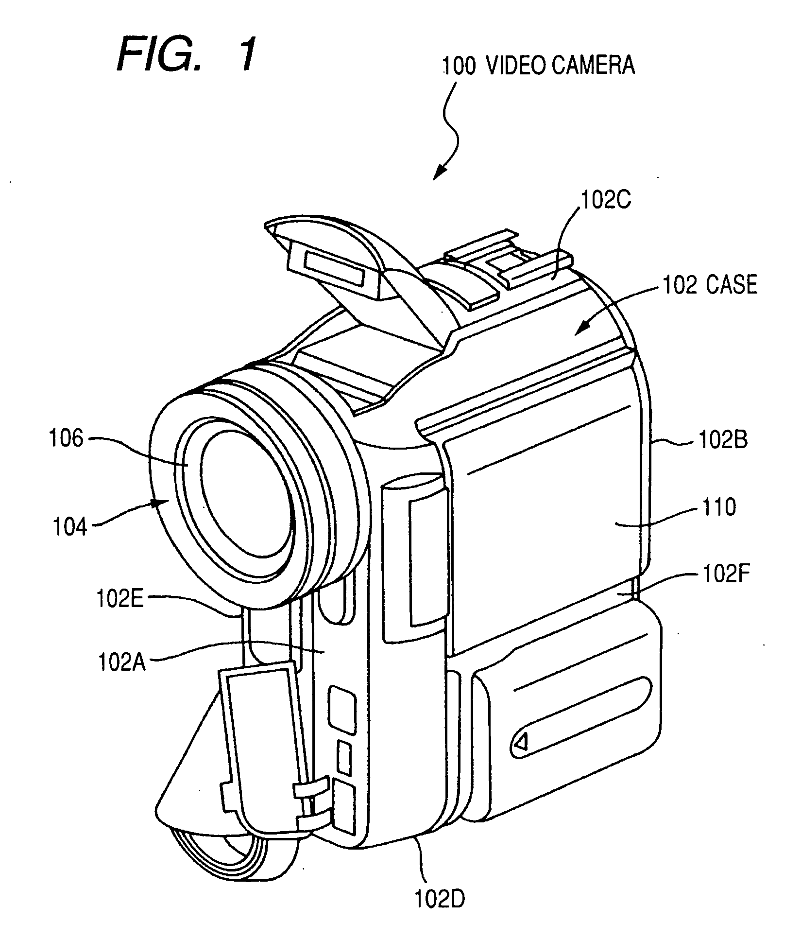
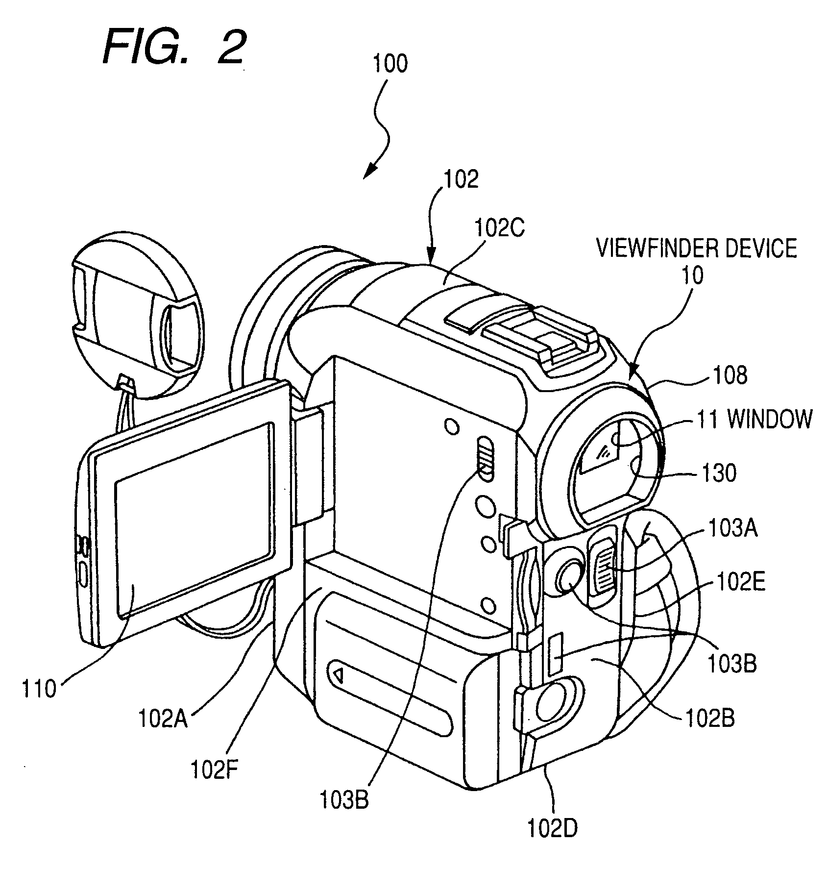
[0033] FIGS. 1 is a perspective of the video camera 100 viewed from the front. FIG. 2 is a perspective view of the video camera 100 viewed from the rear.

[0034]FIG. 3 is a block diagram showing a constitution of a control system of the video camera 100.

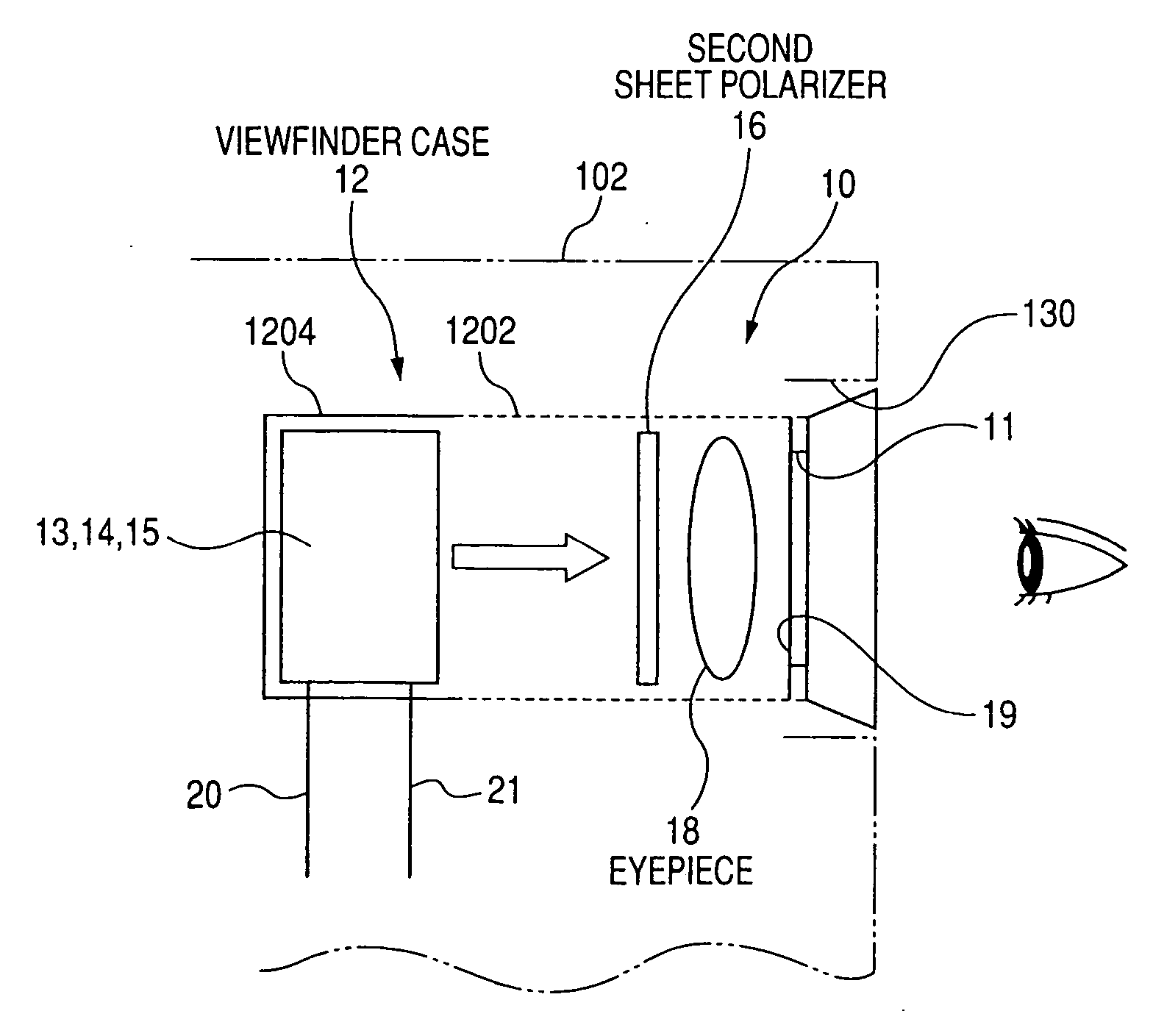
[0035]FIG. 4 is a diagram for explaining a constitution of a viewfinder device 10 of the video camera 100. FIG. 5 is a diagram for explaining a main part in FIG. 4.

[0036] As shown in FIGS. 1 to 3, in this embodiment, the video camera 100 includes a case 102 that constitutes an armor, a photographing optical system 104 that is provided in the case 102 to face forward, an imaging element 107 that is built in the case 102 and images a subject image guided by the photographing optical system 104, and the viewfinder device 10 for visually recognizing an image imaged by the imaging element 107. ...

second embodiment

[0079] the invention will be explained.

[0080]FIG. 7 is a diagram for explaining a constitution of the viewfinder device 10 in the second embodiment. In the following description, components and members same as those in the first embodiment are denoted by the identical reference numerals. Explanations of the components and the members are omitted.

[0081] The second embodiment is a modification of the first embodiment. A sheet polarizer 1602 is provided on at least one of a lens surface of the eyepiece 18 facing the window 11 and a lens surface of the eyepiece 18 facing the transmission liquid crystal panel 13.

[0082] The sheet polarizer 1602 is constituted by, for example, coating a polarizing film over the lens surface or sticking a thin polarizing film over the lens surface.

[0083] The sheet polarizer 1602 constitutes the second sheet polarizer 16.

[0084] It goes without saying that the second embodiment realizes the same advantage as the first embodiment. Moreover, it is possible ...

third embodiment

[0085] the invention will be explained.

[0086]FIG. 8 is a diagram for explaining a constitution of the viewfinder device 10 in the third embodiment.

[0087] The third embodiment is also a modification of the first embodiment. A sheet polarizer 1604 is provided on a surface of the protection plate 19 facing backward from the window 11 or a surface of the protection plate 19 facing the transmission liquid crystal panel 13.

[0088] The sheet polarizer 1602 is constituted by, for example, coating a polarizing film over the surface of the protection plate 19 or sticking a thin polarizing film to the protection plate 19.

[0089] The sheet polarizer 1604 constitutes the second sheet polarizer 16.

[0090] It goes without saying that the third embodiment realizes the same advantage as the first embodiment. Moreover, it is possible to reduce the number of components compared with the first embodiment because the second sheet polarizer 16 is not separately provided. This is advantageous for reducin...


PUM


Abstract

An image pickup apparatus includes a case, a photographing optical system, an imaging element, and a viewfinder device. The viewfinder device includes a viewfinder case, a transmission liquid crystal panel, a lighting device, a first sheet polarizer, and a second sheet polarizer. The viewfinder case includes a case body and a case partitioning member. The lighting device and the first sheet polarizer are supported inside the case partitioning member. The transmission liquid crystal panel is supported inside the case partitioning member with the display surface faced to the window. The second sheet polarizer is supported inside the case body.

Description

CROSS-REFERENCES TO RELATED APPLICATIONS [0001] This application contains subject matter related to Japanese Patent Application JP 2005-008642 filed in the Japanese Patent Office on Jan. 17, 2005, the entire contents of which being incorporated herein by reference. BACKGROUND OF THE INVENTION [0002] 1. Field of the Invention [0003] The present invention relates to an image pickup apparatus including a viewfinder device and a display device that displays images. [0004] 2. Description of the Related Art [0005] As an image pickup apparatus such as a video camera, there is an image pickup apparatus including a case that constitutes an armor, a photographing optical system that is provided in the case, an imaging element that is provided in the case and images a subject image guided by the photographing optical system, and a viewfinder device that is provided in the case and used for visually recognizing an image imaged by the imaging element from an opening of the case. [0006] In the pa...

Claims


Application Information

Patent Timeline
IPC IPC(8): H04N5/222
CPCH04N5/2251H04N23/531
Inventor SAIKI, KUNIHITONAKAYOSHI, HIROKAZUTERADA, TOSHITAKEMATSUNAGA, SHUNICHI
Owner SONY CORP
Learn More