
Access point channel forecasting for seamless station association transition

a technology of access point channel and station association, applied in the field of seamless transition of access point and station association, can solve the problems of compromising station/ap communication, time-consuming connection building process, and loss of station connections

Inactive Publication Date: 2006-08-03
PICCATA FUND LIABILITY
View PDF103 Cites 35 Cited by
  • Summary
  • Abstract
  • Description
  • Claims
  • Application Information

AI Technical Summary

Benefits of technology

[0014] With such arrangements, an AP can broadcast potential alternate communication channels to an STA. In the event that interference on the communication link between the STA and the AP degrade to a point that connectivity is lost, the STA can quickly predict the location of the AP, and resume communication on the link, albeit at an updated frequency, without loss of state. Thus the present invention provides a mechanism for seamlessly transitioning an AP / STA link across channels to compensate for changing RF environments.

Problems solved by technology

The connection building process is time consuming, involving steps of authentication and association of the STA, the creation of forwarding table, the distribution of routing information, etc.
However, a problem arises when changes in the radio environment increase the amount of interference on the transmission channel to a level that compromises station / AP communication.
As a result, station connections are lost and any pending packets are dropped.
Each dropped station must then re-initiate the discovery and association process, causing significant delay in communications with the station and undesirably affecting the overall WLAN performance.
One problem with DFS is that it requires the AP to be able to communicate its intent to switch channels to the STA; The DFS method is ineffective in radio frequency environments when channel interference has increased to levels that disable AP and STA communication.

Method used


Image

  • Access point channel forecasting for seamless station association transition
  • Access point channel forecasting for seamless station association transition
  • Access point channel forecasting for seamless station association transition

Examples


Embodiment Construction

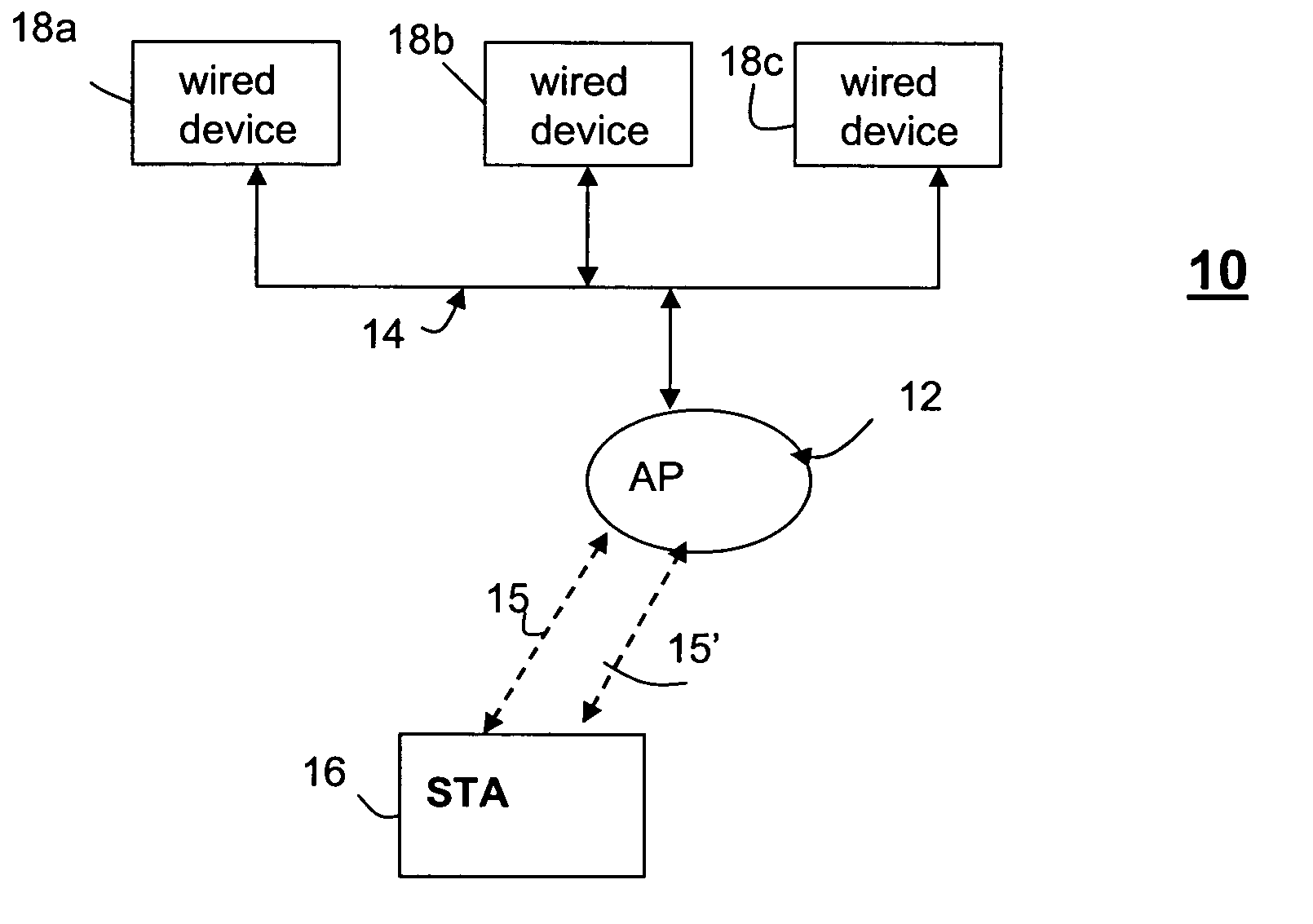
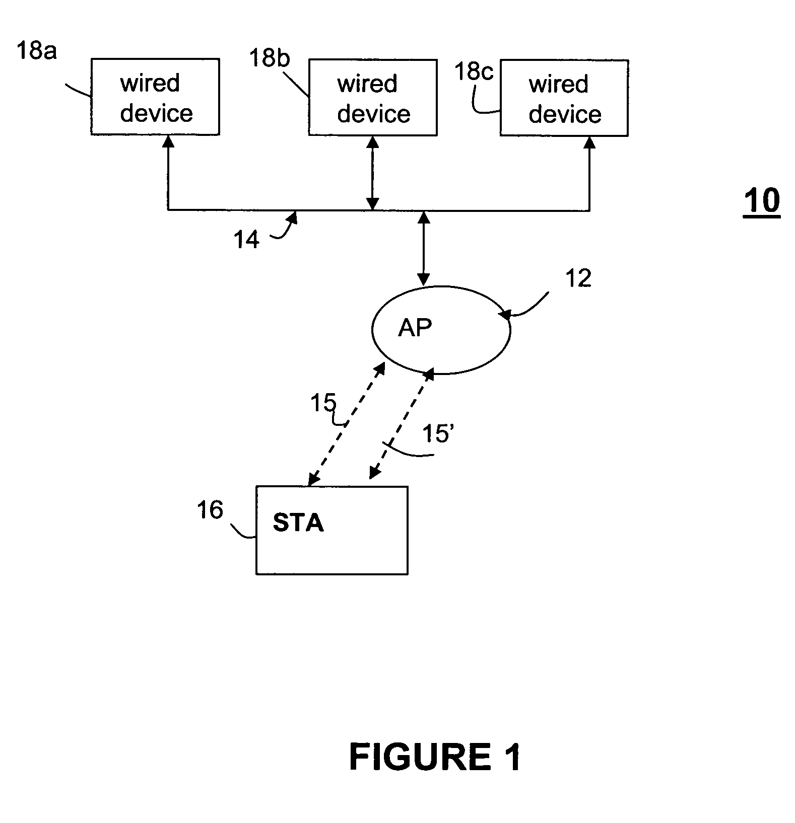
[0020] Referring to FIG. 1 a wireless access point (AP) 12 is operative to provide network access to a wireless end stations (STAs) 16 such as a personal computer, PDA, notebook computer, phone or other wireless device. A STA is typically a mobile device coupled via a radio frequency connection 15 to the AP 12. The AP is typically a stationary device having a wire-line connection with another network device such as devices 18a-18c, which may be, for example, a personal computer, switch, router or server in a network. Communications between the AP and the STAs are typically two-way at a selected radio frequencies, or channels.

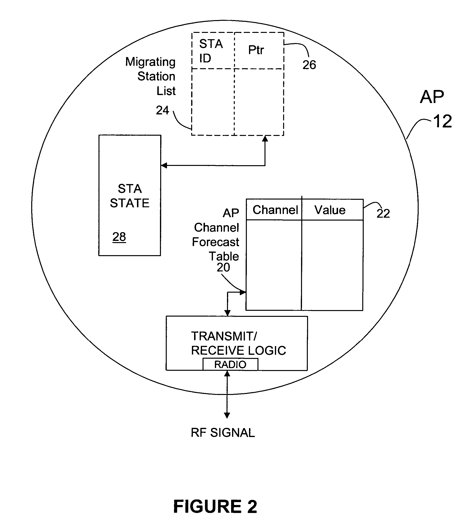
[0021] In one embodiment of the invention, the AP 12 is adapted to recognize and respond to interference in a manner described in patent application attorney docket number 160-091, entitled “Backup Channel Selection in Wireless LANS”, incorporated by reference above. An AP as described therein includes a table of interference profiles stored in memory which are...


PUM


Abstract

Seamless migration of an AP / STA link across channels to compensate for a changing RF environment is achieved by forecasting alternate AP communication channels to an STA prior to loss of connectivity on the link. The AP, when identifying a preferred communication channel, also identifies an alternate communication channel, and communicates this alternate channel to a coupled STA. In the event that communication between the AP and the STA is lost, the STA can quickly predict the new location of the AP, and migrate to the new channel without loss of communication state. The AP is not required to communicate to any STA that it has switched stations. Rather, the fact that the AP has switched is inferred at the STA by the inability of the STA to communicate with the AP. Thus the present invention may be used to preserve link state when a communication channel used by the AP / STA link is blocked.

Description

CROSS-REFERENCE TO RELATED APPLICATIONS [0001] A claim of priority is made under 35 U.S.C. 1.119(e) to U.S. Provisional Patent Application Ser. No. 60 / 649,799 entitled Interference Counter Measures for Wireless LANs, filed Feb. 3, 2005, which is incorporated herein by reference. [0002] This application may be related to patent application Ser. No. ______. Attorney docket number 160-091, entitled “Backup Channel Selection in Wireless LANS”, by Backes et al., filed on even date herewith, which is incorporated herein by reference.FIELD OF THE INVENTION [0003] This invention is generally related to wireless communications, and more particularly to a method and apparatus for seamlessly transitioning an access point and station association when changing transmission channels. BACKGROUND OF THE INVENTION [0004] As it is known in the art, a Wireless Local Area Network (WLAN) is a local-area network that uses high-frequency radio waves, rather than wires, to communicate between nodes. Variou...

Claims


Application Information

Patent Timeline
Patent Type & Authority Applications(United States)
IPC IPC(8): G01R31/08
CPCH04W16/10H04W72/042H04W84/12H04W36/0061H04W36/06H04W76/02H04W76/10H04W72/23
Inventor STEFANI, LAWRENCE V.YUEN, MICHAEL
Owner PICCATA FUND LIABILITY
Learn More