Graphitic nanostructured battery

a graphitic nanostructured, micro-batteries technology, applied in the direction of secondary cell servicing/maintenance, cell component details, cell components, etc., can solve the problems of battery depletion, low efficiency of micro-batteries based on intercalating lithium into glassy carbon, etc., to improve overall battery performance and battery life.

Inactive Publication Date: 2006-08-03
LGS INNOVATIONS +1
View PDF6 Cites 21 Cited by
  • Summary
  • Abstract
  • Description
  • Claims
  • Application Information

AI Technical Summary

Benefits of technology

[0013] Thus, in accordance with the various aspects of the invention, the graphitic nanostructure serves to both deliver an operational feature (i.e., dielectric / electrode) and a control feature of the battery itself. More particularly, with respect to the control feature each nanopost of the graphitic nanostructured surface is disposed in a way such that an electrolyte fluid of the battery is prevented from contacting the electrode, thus preventing discharge of the battery when the battery is not in use. When a voltage is passed over the nanostructured surface, the electrolyte fluid is caused to penetrate the nanostructured surface and to contact the electrode, thus activating the battery. Accordingly, when the activated battery is inserted into an electrical circuit, electrons will flow along the circuit. Advantageously, in addition to forming the battery's electrode, the graphitic nanostructures of the present invention also allow for the control of the graphitic nanostructured battery thereby improving overall battery performance and battery life.

Problems solved by technology

Thus, a battery can become depleted over a period of time even when it is not in active use in an electrical circuit.
However, despite such advantages, the efficiency of microbatteries based on intercalating lithium into glassy carbon is relatively low.

Method used


Image

  • Graphitic nanostructured battery
  • Graphitic nanostructured battery
  • Graphitic nanostructured battery

Examples


Embodiment Construction

[0024] As used herein, unless otherwise specified, a “nanostructure” is a predefined structure having at least one dimension of less than one micrometer. The term “feature pattern” refers to a pattern of nanostructures. The terms “liquid,”“droplet,” and “liquid droplet” are used herein interchangeably. Each of those terms refers to a liquid or a portion of liquid, whether in droplet form or not. The term “graphitic” refers to a three dimensionally ordered array of carbon atoms with planar sheets of hexagonally arrayed atoms stacked in a defined, repeating pattern.

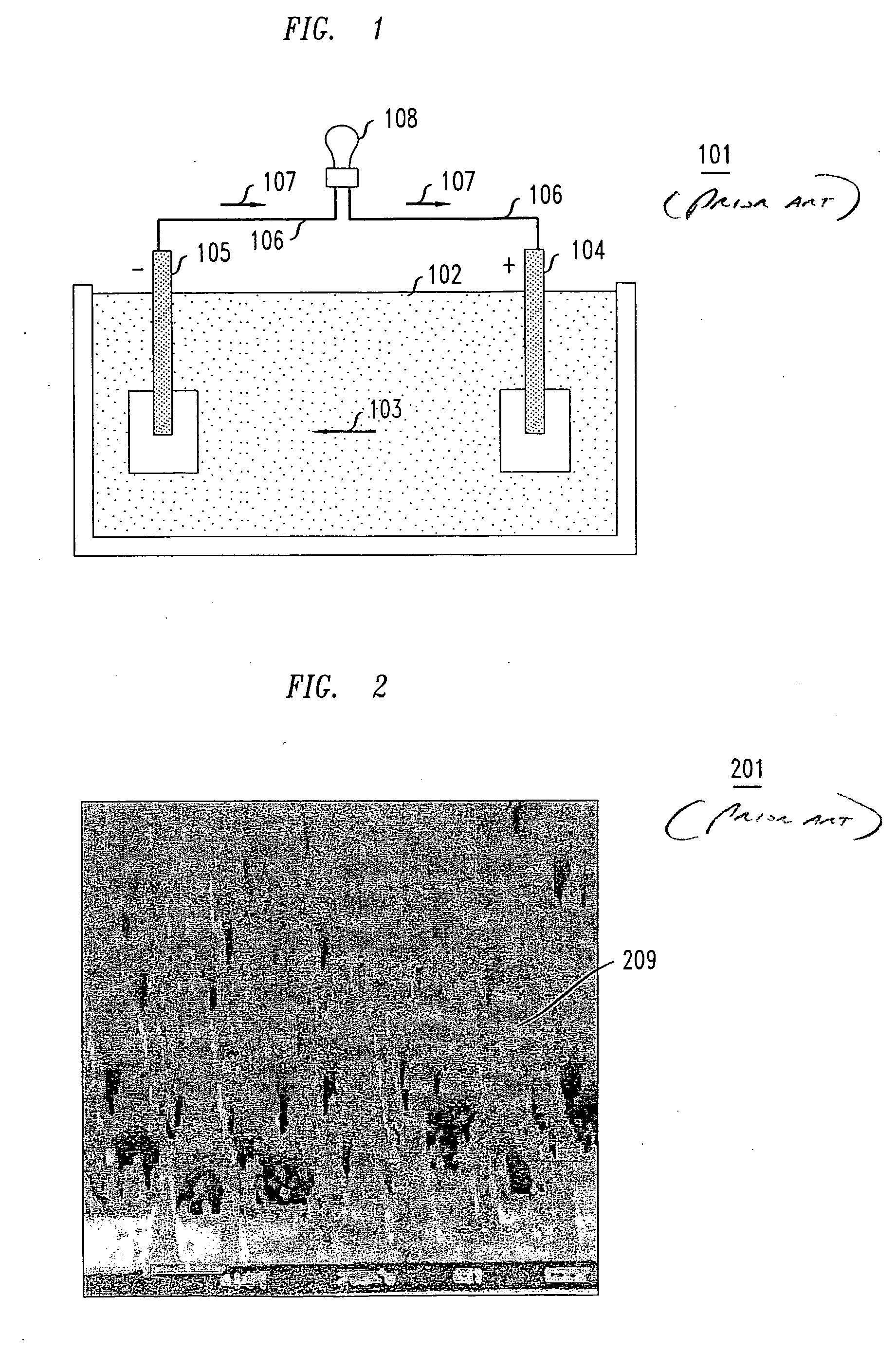
[0025] To better facilitate an understanding of the present invention, a brief discussion on nanostructured surfaces follows. FIG. 2 shows an illustrative nanopost pattern 201 with each nanopost 209 having a diameter of less than 1 micrometer. While FIG. 2 shows nanoposts 209 formed in a somewhat conical shape, other shapes and sizes are also achievable. In fact, cylindrical nanopost arrays have been produced with each nan...


PUM

PropertyMeasurementUnit
sheet sizeaaaaaaaaaa
diameteraaaaaaaaaa
diameteraaaaaaaaaa

Abstract

A method and apparatus are disclosed wherein a battery comprises at least one electrode formed from a graphitic carbon nanostructured surface wherein the nanostructured surface consists of a plurality of nanoposts formed from graphitic carbon such that the graphitic nanoposts serve both as an operational feature (i.e., dielectric/electrode) and control feature of the battery itself. In one embodiment, the nanostructured surface consists of a plurality of nanoposts wherein a select portion of each nanopost is formed to serve as the dielectric of the nanostructured battery, and the balance of each nanopost is utilized to impart the control features to the nanostructured battery.

Description

FIELD OF THE INVENTION [0001] The present invention relates generally to batteries and, more particularly, to microbatteries formed using graphitic nanostructures. BACKGROUND OF THE INVENTION [0002] Many beneficial devices or structures in a myriad of applications rely on batteries as a power source. As shown in FIG. 1, illustrative liquid-cell battery 101, is characterized by an electrolyte liquid 102 which provides a mechanism for an electrical charge to flow in direction 103 between a positive electrode 104 and a negative electrode 105. When battery 101 is inserted into an electrical circuit 106 with illustrative load 108, it completes a loop which allows electrons to flow uniformly in direction 107 around the circuit 106. The positive electrode thus receives electrons from the electrical circuit 106. These electrons then react with the materials of the positive electrode 104 in reduction reactions that generate the flow of a charge to the negative electrode 105 via ions in the e...

Claims


Application Information

Patent Timeline
Patent Type & Authority Applications(United States)
IPC IPC(8): H01M2/14H01M4/62H01M4/66H01M10/44H01M4/58
CPCB82Y30/00H01M4/0471H01M4/049H01M4/583H01M4/587H01M6/40H01M10/04H01M10/0472H01M10/058Y02E60/10
Inventor KOLODNER, PAUL ROBERTKRUPENKINE, THOMAS NIKITALYONS, ALAN MICHAELPAU, STANLEYTAYLOR, JOSEPH ASHLEYVYAS, BRIJESH
Owner LGS INNOVATIONS
Why Eureka
Try Eureka