Radio communication apparatus and pilot symbol transmission method
a technology of radio communication apparatus and pilot symbol, which is applied in the direction of transceiving monitoring, orthogonal multiplex, multiplex communication, etc., can solve the problems of data symbol proportion, and achieve the effect of reducing channel capacity and not reducing information transmission efficiency
- Summary
- Abstract
- Description
- Claims
- Application Information
AI Technical Summary
Benefits of technology
Problems solved by technology
Method used
Image
Examples
embodiment 1
[0033] Embodiment 1 of the invention will specifically be described below with reference to the accompanying drawings. In the following descriptions, a base station apparatus and mobile station apparatus are assumed to perform communications in an OFDM (Orthogonal Frequency Division Multiplexing) system, and transmission of the pilot symbol on the uplink channel from the mobile station apparatus to base station apparatus will be described.
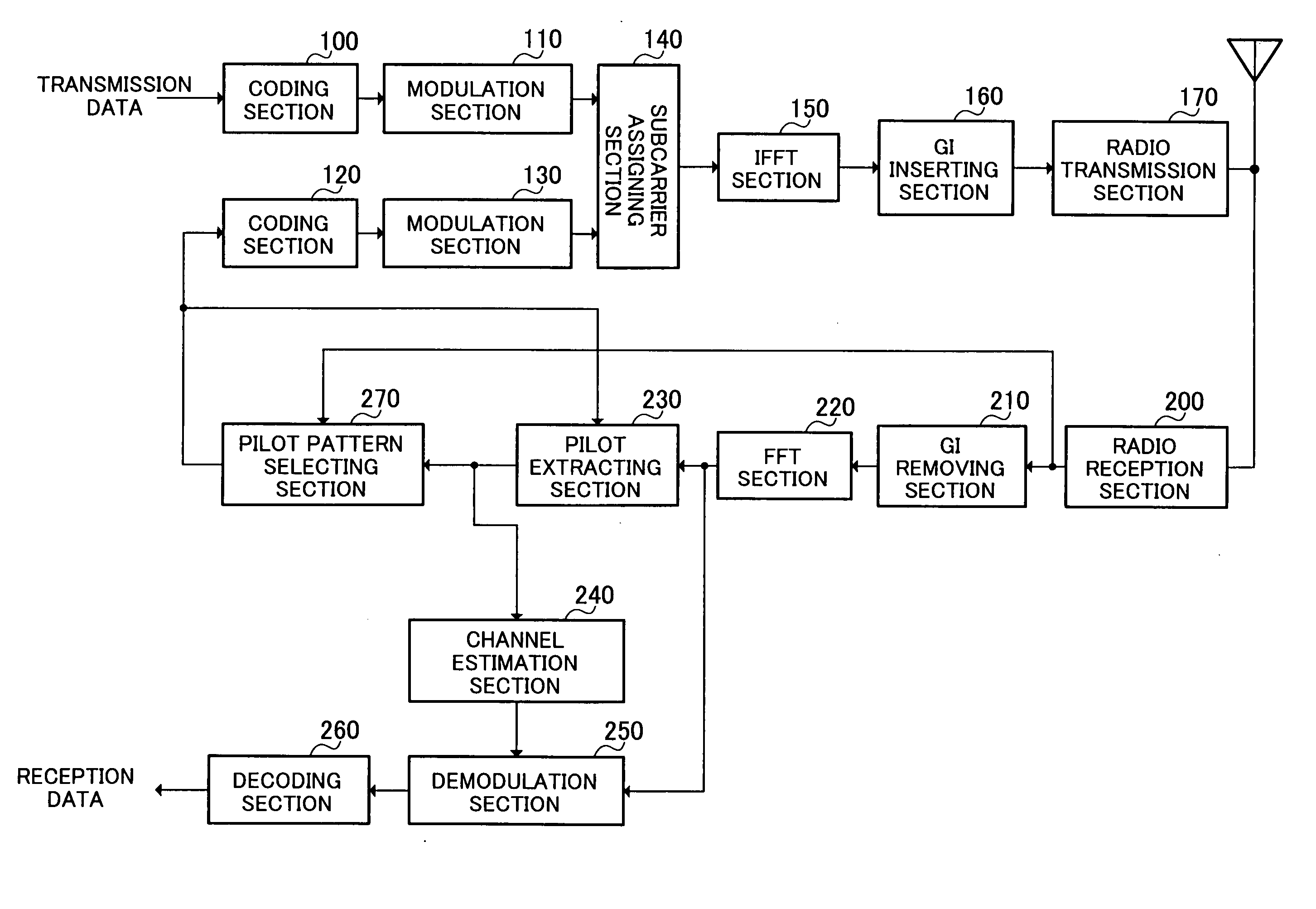
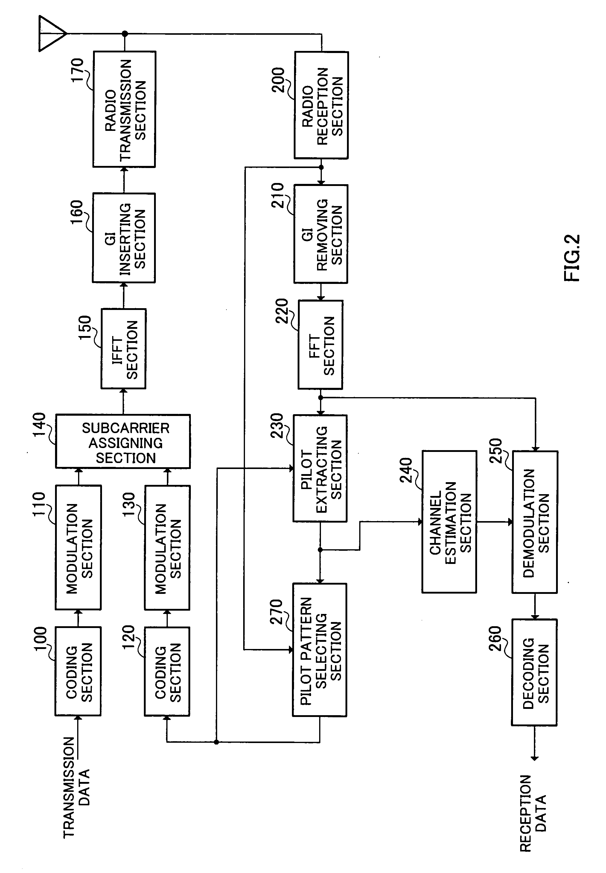
[0034]FIG. 2 is a block diagram illustrating a configuration of principal part of a base station apparatus according to Embodiment 1 of the invention. The base station apparatus shown in the figure has a transmission section comprised of coding section 100, modulation section 110, coding section 120, modulation section 130, subcarrier assigning section 140, IFFT (Inverse Fast Fourier Transform) section 150, GI (Guard Interval) inserting section 160 and radio transmission section 170, and a reception section comprised of radio reception section 200...
embodiment 2
[0111] The influence of the accuracy of channel estimation using the pilot symbol on the bit error rate varies between modulation schemes. In other words, as the modulation scheme has a larger modulation level, higher accuracy is required in channel estimation. Particularly, in QAM modulation such as 16QAM and 64QAM, since judgment on amplitude is required as well as judgment on phase upon demodulation, high accuracy is required in channel estimation. Further, to achieve high accuracy in channel estimation, it is necessary to increase a proportion of pilot symbols (i.e. density of pilot symbols) in a frame.
[0112] Therefore, in this Embodiment, a pilot pattern is selected further considering the modulation scheme in addition to three parameters (delay dispersion, moving speed of a mobile station apparatus and other-cell interference) used in Embodiment 1. In addition, in following descriptions, as in Embodiment 1, a base station apparatus and mobile station apparatus are assumed to ...
embodiment 3
[0130] Embodiments 1 and 2 describe transmission of pilot symbol on the uplink channel from the mobile station apparatus to the base station apparatus. This Embodiment describes transmission of pilot symbol on the downlink channel from the base station apparatus to the mobile station apparatus. Further, in this Embodiment, the base station apparatus and mobile station apparatus are assumed to perform communications in the OFDM system as in Embodiments 1 and 2, and further, perform communications for each time slot as a transmission unit basis.
[0131]FIG. 14 is a block diagram illustrating a configuration of principal part of a base station apparatus according to Embodiment 3. In FIG. 14, the same structural elements as in Embodiment 1 (FIG. 2) are assigned the same reference numerals to omit descriptions thereof.
[0132] Coding sections 100-1 to 100-K and modulation sections 110-1 to 110-K perform coding and modulation on transmission data 1 to K to mobile station apparatuses 1 to K,...
PUM
 Abstract
Description
Claims
Application Information
 - R&D
- Intellectual Property
- Life Sciences
- Materials
- Tech Scout
- Unparalleled Data Quality
- Higher Quality Content
- 60% Fewer Hallucinations
Browse by: Latest US Patents, China's latest patents, Technical Efficacy Thesaurus, Application Domain, Technology Topic, Popular Technical Reports.
© 2025 PatSnap. All rights reserved.Legal|Privacy policy|Modern Slavery Act Transparency Statement|Sitemap|About US| Contact US: help@patsnap.com


