Ofdm reception device and ofdm reception method

a technology of reception device and reception method, which is applied in the direction of digital transmission, transmission monitoring, electrical apparatus, etc., can solve the problems of high characteristic deterioration, collision (hit), and high probability of errors in llr values, so as to improve error correction performance, correct detection of symbols, and improve error correction performance

Inactive Publication Date: 2006-08-03
PANASONIC CORP
View PDF7 Cites 68 Cited by
  • Summary
  • Abstract
  • Description
  • Claims
  • Application Information

AI Technical Summary

Benefits of technology

[0019] Thus, the reception power of the signal at the detected interference position and the reception power value of the measured desired signal are compared for each subcarrier and whether the reception power of symbols of the respective subcarriers should be used as they are or set to 0 based on the comparison result, and therefore it is possible to correctly detect symbols to be treated as i

Problems solved by technology

In this case, this means that the SNR (Signal to Noise Ratio) is lower than those of surrounding subcarriers, and therefore errors are likely to occur in the LLR values of symbols “0” and “1”.
Furthermore, when an error occurs in a symbol decision, the influence of this error may also affect LLR values of symbols of other subcarriers.
Normally, a user's hopping patterns and resource assignment are determined at random in the own cell and other cells, and therefore collision (hit) may occur accidentally at a certain subcarrier at a certain time point.
As described above, the turbo code and LDPC code are designed on the premise of an AWGN channel and such a hit is not

Method used


Image

  • Ofdm reception device and ofdm reception method
  • Ofdm reception device and ofdm reception method
  • Ofdm reception device and ofdm reception method

Examples


embodiment 1

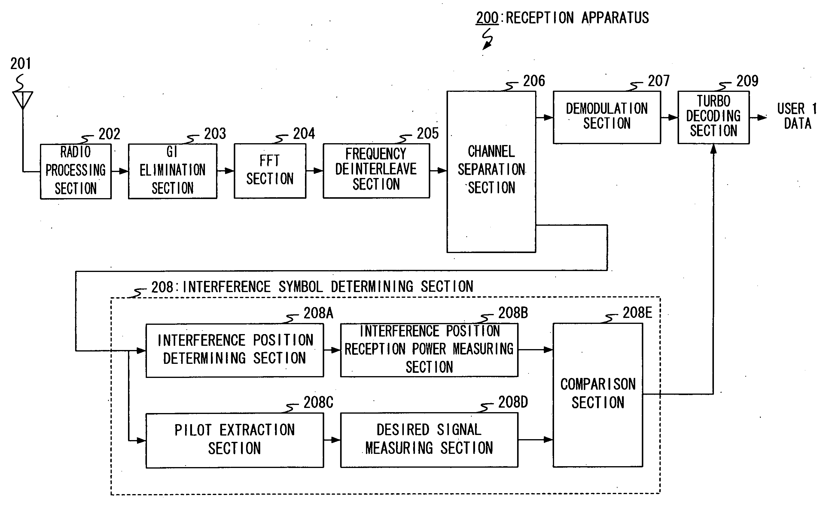
[0042] With reference to the attached drawings, embodiments of the present invention will be explained in detail below. FIG. 7 is a block diagram showing the configuration of a transmission apparatus according to a frequency hopping OFDM scheme (hereinafter referred to as “FH-OFDM scheme”) according to an embodiment of the present invention and FIG. 8 is a block diagram showing the configuration of a reception apparatus according to an FH-OFDM scheme according to this embodiment related to user 1. Here, a transmission apparatus 100 is provided for a base station and a reception apparatus 200 is provided for a communication terminal.

[0043] The transmission apparatus 100 provided for the base station is principally constructed of turbo coding sections 101-1, 101-2, modulation sections 102-1, 102-2, subcarrier mapping sections 103-1, 103-2, a multiplexer 104, a frequency interleave section 105, a serial / parallel (S / P) conversion section 106, an inverse fast Fourier transform (IFFT) se...

embodiment 2

[0070] Embodiment 1 above mainly assumes a PSK-based modulation scheme. According to Embodiment 1, the position of interference is set by notifying an interference position and then the magnitude of an interference signal is estimated from a difference between the received signal and desired signal. However, it is difficult to apply this method to a QAM-based modulation scheme in which power of each symbol of a received signal changes depending on data.

[0071] Therefore, as shown in FIG. 10 and FIG. 11, this embodiment assumes that the positions of subcarriers to which a pilot sequence is assigned are the same for the own cell and other cell and assigns sequences orthogonal to their respective sequences. Resource assignment of users and pilots of a base station of the own cell is shown in FIG. 10 and that in the other cell is shown in FIG. 11.

[0072] By so doing, it is possible to measure average power of the own cell and other cell by the terminals of user 1 and user 2.

[0073] Furt...

embodiment 3

[0076] In Embodiments 1 and 2, an interference position can be detected by decoding an interference position notification signal on the receiving side. This embodiment decides an interference position and estimates interference power by deciding power of a received signal against a threshold.

[0077] A transmission apparatus of this embodiment is shown in FIG. 14. Unlike the transmission apparatus 100 in FIG. 7, no adjacent interference position notification signal generation section 111 is connected to the transmission apparatus 400.

[0078] Suppose the reception apparatus sets a threshold assuming that a value obtained by subtracting power of an actually received symbol from power of the received signal obtained from a pilot is interference signal power+noise power per symbol and treats a symbol position exceeding the threshold as an interference received symbol.

[0079] This interference power+noise power per symbol can be expressed by the following Expression:

ΔPr(k,m)=(|r(k,m)|−|h...


PUM


Abstract

An interference symbol determining section 208 compares reception power of a signal at an interference position measured by an interference position reception power measuring section 208B with a reception power value of a desired signal measured by a desired signal measuring section 208D for each subcarrier, thereby determines symbols which should be actually treated as interference symbols and outputs the symbols to a turbo decoding section 209. The turbo decoding section 209 determines whether to calculate LLR values of symbols of each subcarrier signal input from a demodulation section 207 or set the LLR values to “0” based on the comparison result of the interference symbol determining section 208 and executes decoding processing.

Description

TECHNICAL FIELD [0001] The present invention particularly relates to an OFDM reception apparatus and OFDM reception method used for an OFDM system according to a frequency hopping scheme. BACKGROUND ART [0002] In recent years, a mobile communication system based on an OFDM scheme using frequency hopping is under study. An OFDM system using frequency hopping carries out communication using different hopping patterns among a plurality of cells and thereby averaging interference among cells. [0003] A mobile communication system using a multicarrier scheme including a frequency hopping OFDM scheme adopts a coding scheme premised on MAP (Maximum a posteriori) decoding using a soft decision value such as turbo code or LDPC (Low Density Parity Check) code for coding of transmission information. [0004] Furthermore, turbo code decoding processing is derived on the assumption that a transmission path is in an AWGN (Additive White Gaussian Noise) environment and can calculate, for example, an ...

Claims


Application Information

Patent Timeline
IPC IPC(8): H04B17/00H04B1/713H04B1/715H04J99/00H04L27/26
CPCH04L27/2647
Inventor YOSHII, ISAMUFUKUOKA, MASARU
Owner PANASONIC CORP
Why Eureka
Try Eureka