Method for real-time well-site interpretation of array resistivity log data in vertical and deviated wells

a technology of array resistivity and log data, which is applied in the direction of instruments, waterlogging seismology, and reradiation, can solve the problems of thin invaded layers, inability to meet real-time processing requirements, and time-consuming 3/b>-d inversion techniques

Active Publication Date: 2006-08-03
BAKER HUGHES INC
View PDF20 Cites 42 Cited by
  • Summary
  • Abstract
  • Description
  • Claims
  • Application Information

AI Technical Summary

Benefits of technology

[0012] Another embodiment of the invention is a machine readable medium that includes instructions enabling the processor to control the data acquisition and process the data. The machine readable medium may include ROMs, EPROMs, EAROMs, Flash Memories and Optical disks.

Problems solved by technology

One problem with inversion is that the earth is characterized by a 2-D model (layers with radial changes in resistivity within each layer) or a 3-D model (layers with radial changes in resistivity within each layer, and a relative dip between layers and the borehole).
A rigorous 2-D or 3-D inversion techniques would be quite time consuming and impractical for wellsite implementation.
The main shortcomings of this method are it does not satisfy a real-time processing requirements and it may provide inaccurate results in thin invaded layers due to coupling between shoulder beds and invasion in the adjacent layers.
So it leads to significant errors in thin invaded layers.
To check the quality and correct inversion results, Griffiths et al. suggest to run a rigorous 2-D inversion which makes this technique is not applicable to even post-acquisition well-site processing.
Correction is made only for the invasion effect and could be approximate and lead to incorrect 1-D inversion results even in relatively thick (˜5 ft or 1.5 m) invaded formations.
In addition, the inversion process may become unstable at layer boundaries, so that significant post inversion processing is often required.

Method used


Image

  • Method for real-time well-site interpretation of array resistivity log data in vertical and deviated wells
  • Method for real-time well-site interpretation of array resistivity log data in vertical and deviated wells
  • Method for real-time well-site interpretation of array resistivity log data in vertical and deviated wells

Examples


Embodiment Construction

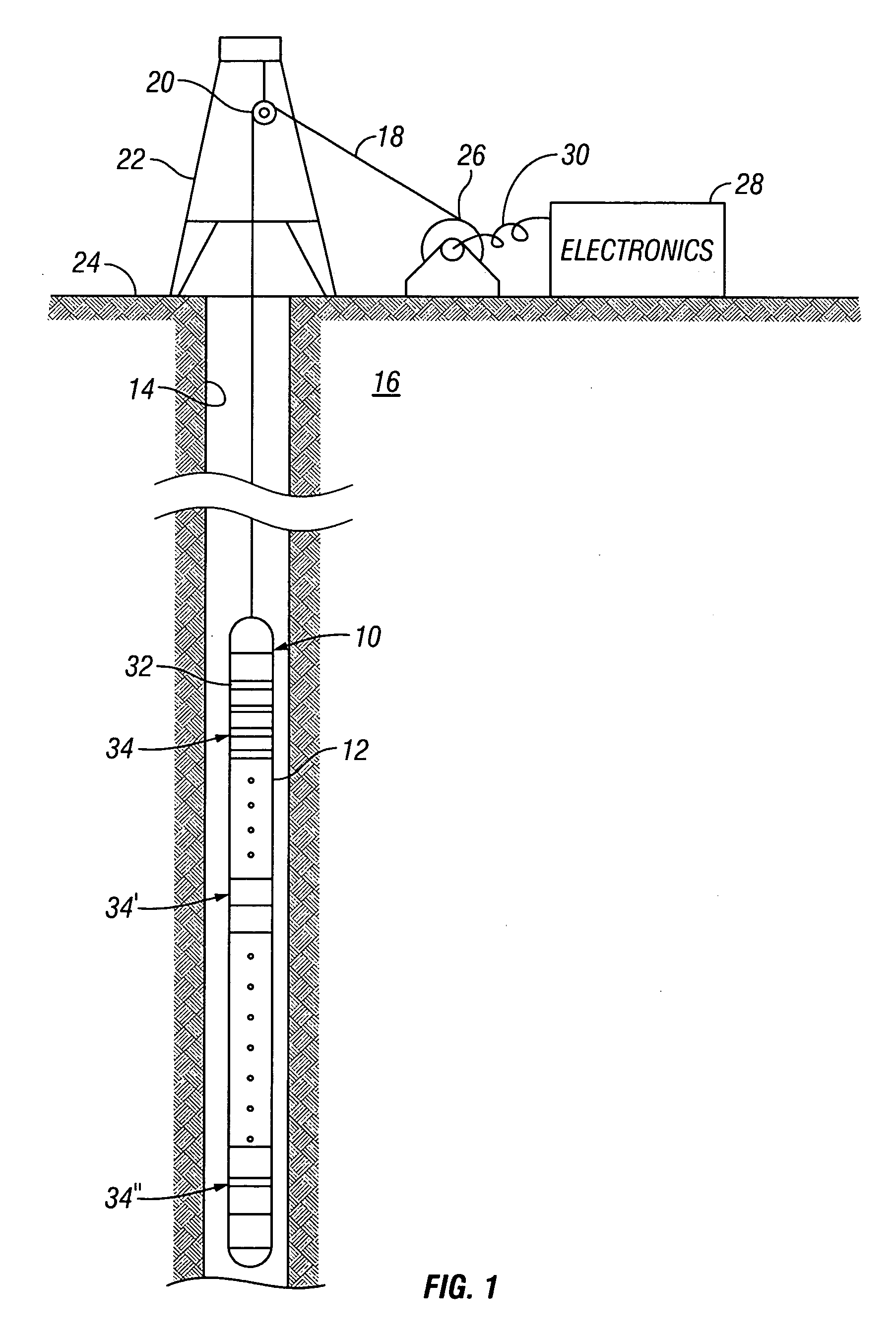
[0024] Referring now to FIG. 1, an exemplary prior art differential array resistivity instrument 10 will be described. Such a configuration has been described in U.S. Pat. No. 6,060,885 to Tabarovsky et al. having the same assignees as the present invention and the contents of which are incorporated herein by reference. The instrument 10 is shown disposed in a borehole 14 penetrating an earth formation 16 and supported by a wire cable 18. The cable 18 is supported and guided by a sheave wheel 20 suspended from a well structure 22 in place on the earth's surface 24 over the wellbore 14. The cable 18 is stored on a cable drum 26 which is controlled at the surface to lower and raise the differential array instrument 12 within the wellbore 14 at a predetermined logging speed. Commands for controlling the operation of the instrument 12 and the data collected by the instrument are transmitted electrically through the cable 18 and via interconnecting cable 30 to an electronics package 28 l...


PUM


Abstract

A method and apparatus for real-time well-site interpretation of array resistivity log data. An inversion of data with different depths of investigation is carried out after data shoulder-bed correction. The formation model used by inversion is constructed with the layer boundaries obtained from an imaging tool or other log measurements.

Description

CROSS-REFERENCES TO RELATED APPLICATIONS [0001] This application claims priority from U.S. Provisional Patent Application Ser. No. 60 / 648,563 filed on Jan. 31, 2005.BACKGROUND OF THE INVENTION [0002] 1. Field of the Invention [0003] The invention is related generally to the field of interpretation of measurements made by well logging instruments for the purpose of determining the properties of earth formations. More specifically, the invention is related to a method for determination of formation resistivity using array resistivity data in vertical and deviated wells. [0004] 2. Background of the Art [0005] Electromagnetic induction, wave propagation, and galvanic logging tools are commonly used for determination of electrical properties of formations surrounding a borehole. These logging tools give measurements of apparent resistivity (or conductivity) of the formation that when properly interpreted are diagnostic of the petrophysical properties of the formation and the fluids there...

Claims


Application Information

Patent Timeline
Patent Type & Authority Applications(United States)
IPC IPC(8): G01V3/18
CPCG01V3/265
Inventor FRENKEL, MICHAEL A.
Owner BAKER HUGHES INC
Why Eureka
Try Eureka