
Tool for processing software programs using modified live-ness definition

a software program and live-ness technology, applied in the field of computer software systems, can solve the problems of complicated flow graphs, inconvenient processing of programs based on such flow graphs, and insufficient processing of programs, so as to achieve the effect of simplifying the processing of programs

Inactive Publication Date: 2006-08-03
MICROSOFT TECH LICENSING LLC
View PDF22 Cites 11 Cited by
  • Summary
  • Abstract
  • Description
  • Claims
  • Application Information

AI Technical Summary

Benefits of technology

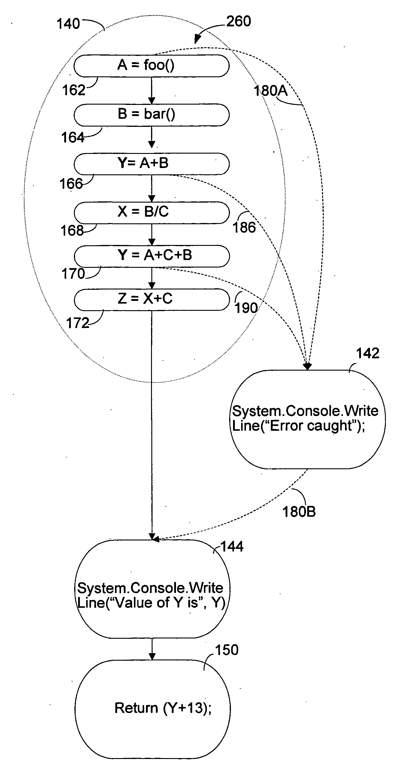
[0024] This patent application describes a method of processing a software program that uses a modified definition of live-ness that is useful in processing programs having asynchronous transfer. Described embodiments include use of this method to form an intermediate representation of programs having protected regions and protector regions. The intermediate representation has a reduced number of edges representing asynchronous flow, which simplifies processing of the program yet allows processing to be performed using conventional tools.

Problems solved by technology

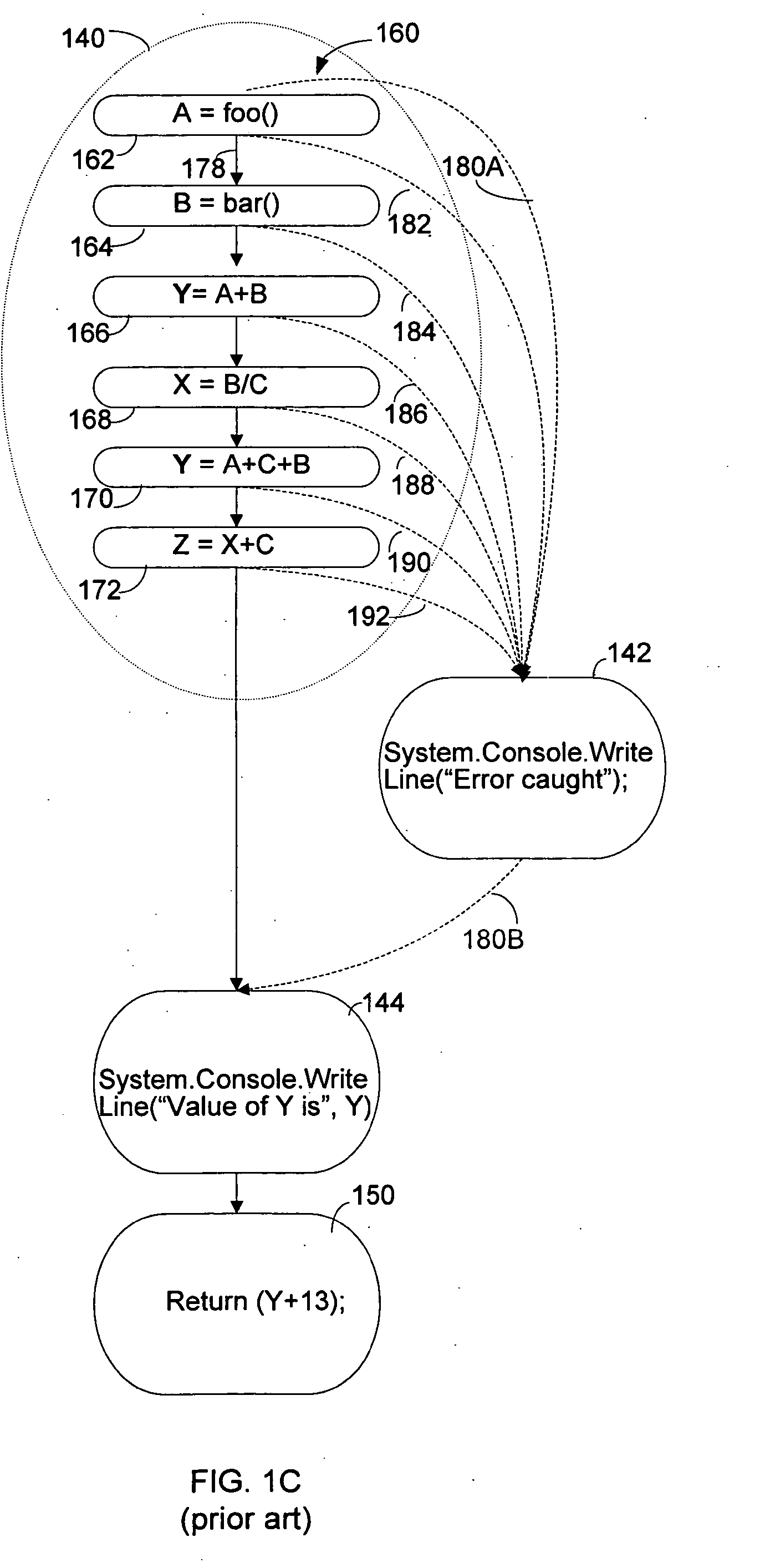
However, a drawback of adding asynchronous edges using the “all possible edges” approach illustrated in FIG. 1C is the resulting complexity of the flow graph.
As a result, adding all possible asynchronous edges to a flow graph greatly complicates the flow graph.
Processing a program based on such a flow graph may therefore take considerable time or computer resources.
However, to compensate, tools processing programs based on these flow graphs do not perform operations on instructions in the try regions that rely on an accurate representation of all possible flow paths.
While processing a program in this fashion may be faster or simpler, the benefits of the software tools are not achieved.

Method used


Image

  • Tool for processing software programs using modified live-ness definition
  • Tool for processing software programs using modified live-ness definition
  • Tool for processing software programs using modified live-ness definition

Examples


Embodiment Construction

[0041] We have overcome limitations of the prior art by creating an intermediate representation of software that includes indications of the effect of asynchronous transfers. The intermediate representation may include less than all possible asynchronous edges, thereby simplifying the intermediate representation of the program and any processing based on it and ensuring accurate operation of tools that process the program using the intermediate representation. Effects of asynchronous transfers may be indicated in one or more ways. In some embodiments, the indication of the effect of an asynchronous transfer is in the form of an edge directly depicting the asynchronous transfer. In other embodiments, the effect of the asynchronous transfer is indicated by information stored in connection with a variable used in the program. The information may be stored in a symbol table or a pseudoinstruction in the intermediate representation. Multiple forms may be used to indicate the effect of an...


PUM


Abstract

A compiler that forms an intermediate representation of a program using a flow graph with less than all possible edges used to model asynchronous transfers within the program. The flow graph is formed in multiple phases. In one phase, the flow graph is formed without modeling asynchronous transfers. In later phases, representations of the effects of the asynchronous transfers are selectively added. As part of the later phases, edges modeling a possible asynchronous transfer are added to the flow graph following definitions in protected regions of variables that are live outside the protected region. A modified definition of live-ness of a variable is used to incorporate use of the variable in any region, including the protected region, following an asynchronous transfer. Edges from the protected region are also added to the model if the only use of the defined variable is in a handler.

Description

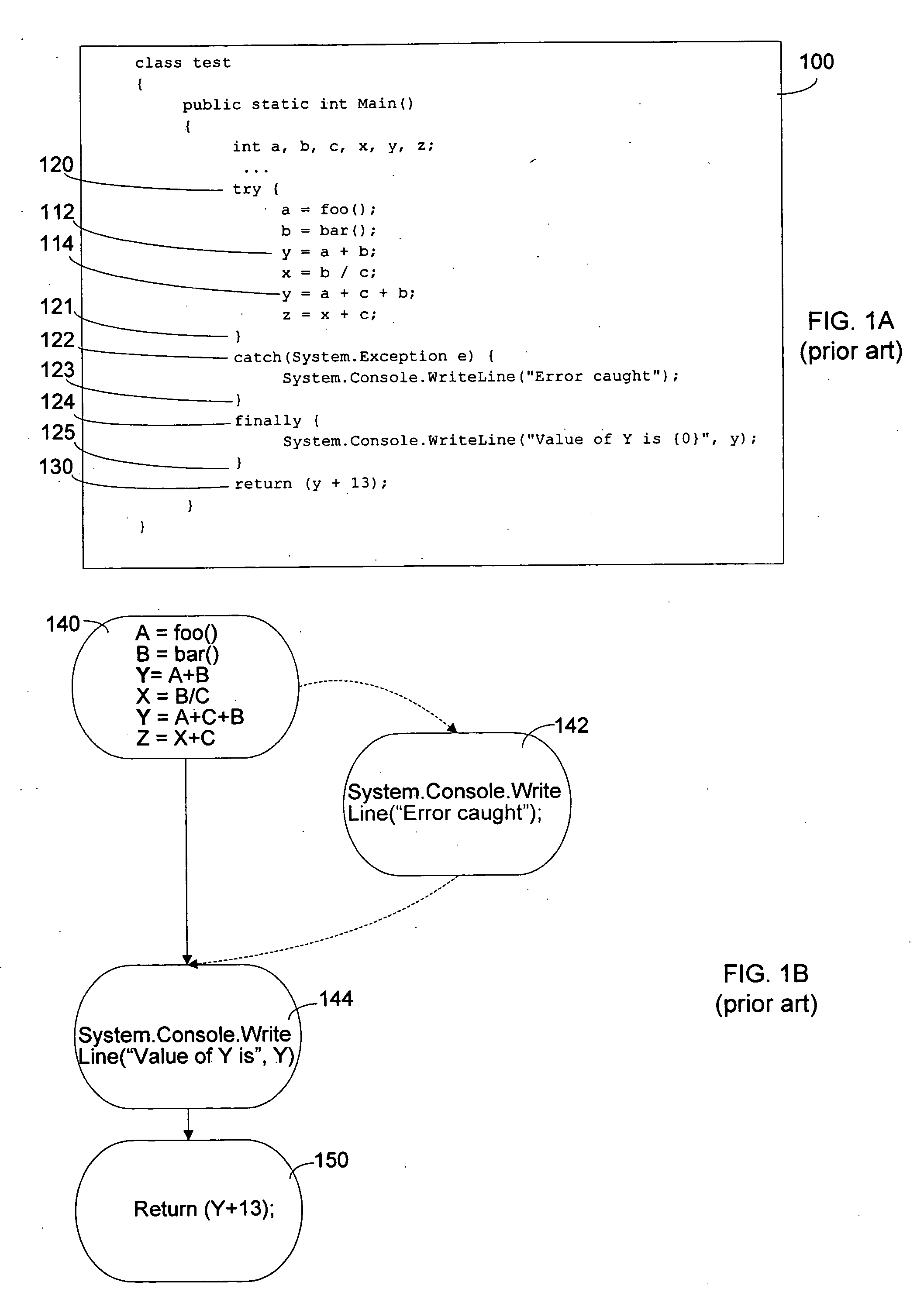
BACKGROUND OF INVENTION [0001] 1. Field of Invention [0002] This invention relates generally to computer software systems and more specifically to computer software systems that processes computer programs prior to execution. [0003] 2. Discussion of Related Art [0004] Computer programs are often written as a series of instructions. Some instructions may specify operations that are performed when the program is executed. Other instructions may control program flow by specifying the order or conditions under which other instructions are executed. Yet other instructions may specify parameters of execution of the program, such as how information representing variables in the program is stored in memory attached to a processor executing the program. [0005] In high level programming languages, the instructions do not necessarily correspond in a one-to-one relationship to instructions that can be executed by the platform on which the software will be executed. Rather, the instructions may ...

Claims


Application Information

Patent Timeline
Patent Type & Authority Applications(United States)
IPC IPC(8): G06F9/44
CPCG06F8/433G06F9/4436G06F9/4494G06F9/30
Inventor BEARMAN, IAN M.RADIGAN, JAMES J.
Owner MICROSOFT TECH LICENSING LLC
Learn More