Banded door sill base and door sill assembly, and method of forming same

a door sill and banded technology, applied in the direction of sills/thresholds, building components, constructions, etc., can solve the problems of poor fit between the base plate and the door frame, low thermal conductivity of wood, and high dimensional stability of wood, so as to prevent linear expansion of the central portion

Inactive Publication Date: 2006-08-10
YOUNG ROBERT H
View PDF18 Cites 56 Cited by
  • Summary
  • Abstract
  • Description
  • Claims
  • Application Information

AI Technical Summary

Benefits of technology

[0005] The present invention is directed to a banded doorsill base for disposition between a pair of doorjambs of a door frame. The doorsill base includes an elongate central portion, and first and second strips. The central portion is formed from a material having a first coefficient of linear expansion, and has a generally rectangular configuration in plan view with first and second opposite sides and first and second opposite ends. The first strip is attached to and extends along the first side of the central portion. The second strip is attached to and extends along the second side of the central portion. The first and second strips are formed from a material having a second coefficient of linear expansion less than the first coefficient. The first and second strips constrain the central portion and substantially prevent linear expansion of the central portion.
[0007] A method of forming a banded doorsill base is disclosed. A central portion formed from one of a polymer material and a wood fiber-resin composite and having a first coefficient of linear expansion is provided. A first wood strip is adhesively bonded to a first edge, of the central portion. A second wood strip is adhesively bonded to a second edge of the central portion opposite the first edge. The first and second wood strips have a second coefficient of linear expansion less than the first coefficient so that the first and second wood strips substantially prevent linear expansion of the central portion.

Problems solved by technology

In addition, wood has a relatively low thermal conductivity and high dimensional stability.
However, wooden base plates are subject to degradation from wood rot.
This, in turn, may result in a poor fit between the base plate and the door frame, particularly with door sills having a length of six feet or more.
Therefore, non-wooden base plates have not proven practical or cost efficient.

Method used


Image

  • Banded door sill base and door sill assembly, and method of forming same
  • Banded door sill base and door sill assembly, and method of forming same
  • Banded door sill base and door sill assembly, and method of forming same

Examples


first embodiment

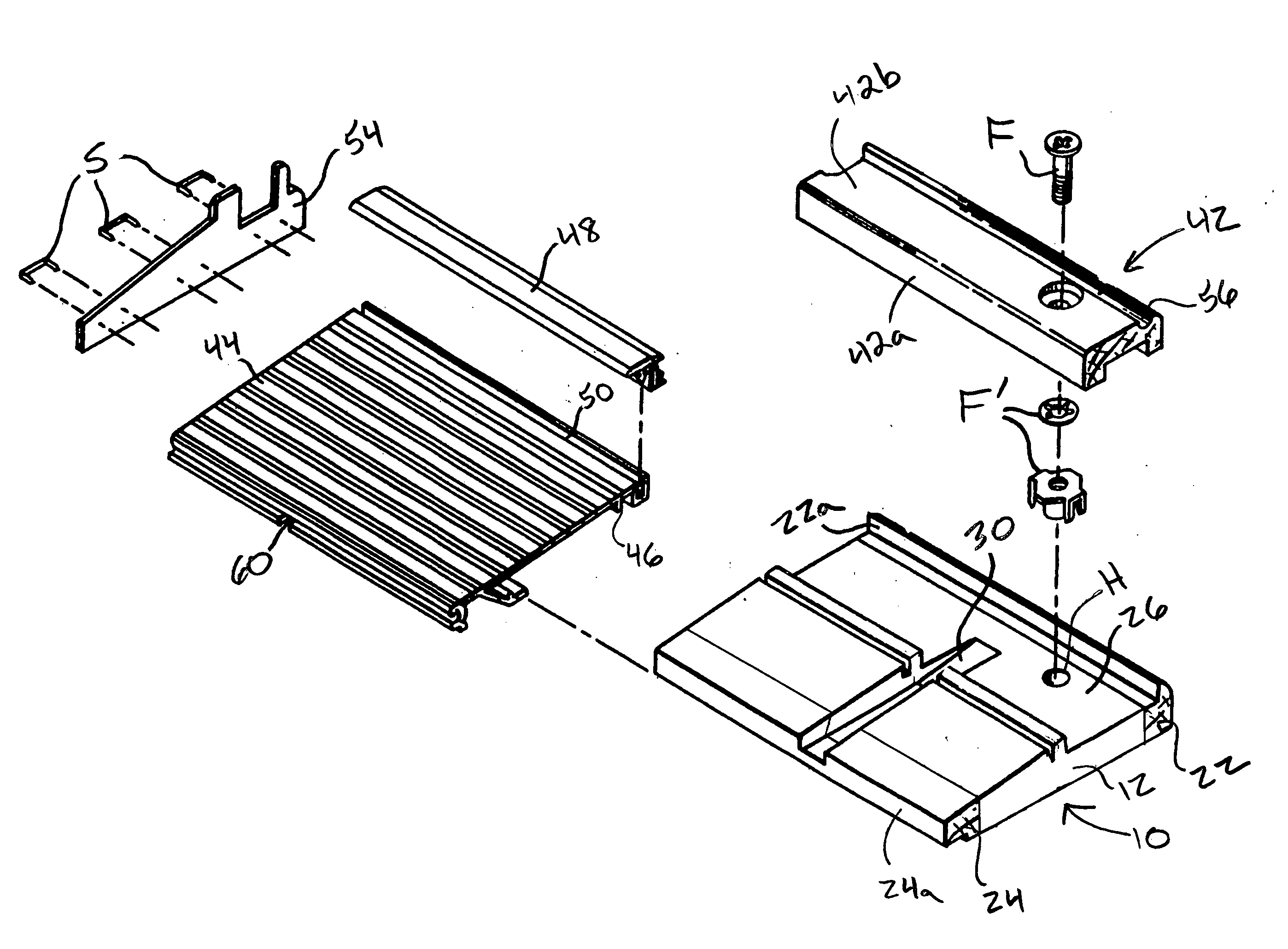
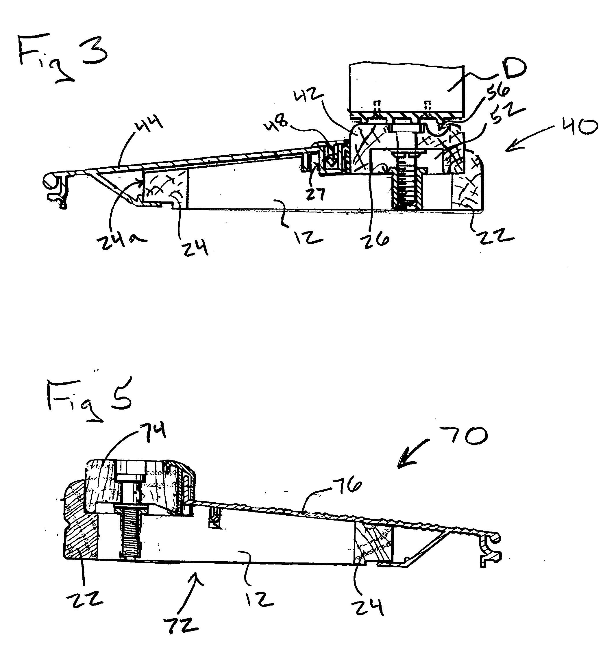
[0023] A doorsill assembly 40 according to the present invention is best shown in FIGS. 3 and 4. Assembly 40 includes an elongated threshold member 42 disposed over and adjustably connected to base 10. Assembly 40 also includes an elongated weather cover panel 44, preferably constructed of an aluminum alloy. Cover panel 44 is attached to base 10 so as to overlie and extend from an exteriorly disposed edge 24a of second strip 24 and interface wall 27. Cover panel 44 may include a rib 46 that is received in groove 29 of base 10. Cover panel 44 forms a foot tread. An elongated gasket 48, preferably a compressible, resilient vinyl gasket, is connected along an interior facing edge portion 50 of cover panel 44, and extends along a narrow gap between interface wall 29 and an exterior facing side 42a of threshold member 42 to inhibit seepage of water therethrough.

[0024] A series of conventional, adjustable fasteners F connect threshold member 42 to planar surface 26 of base. Accordingly, p...

second embodiment

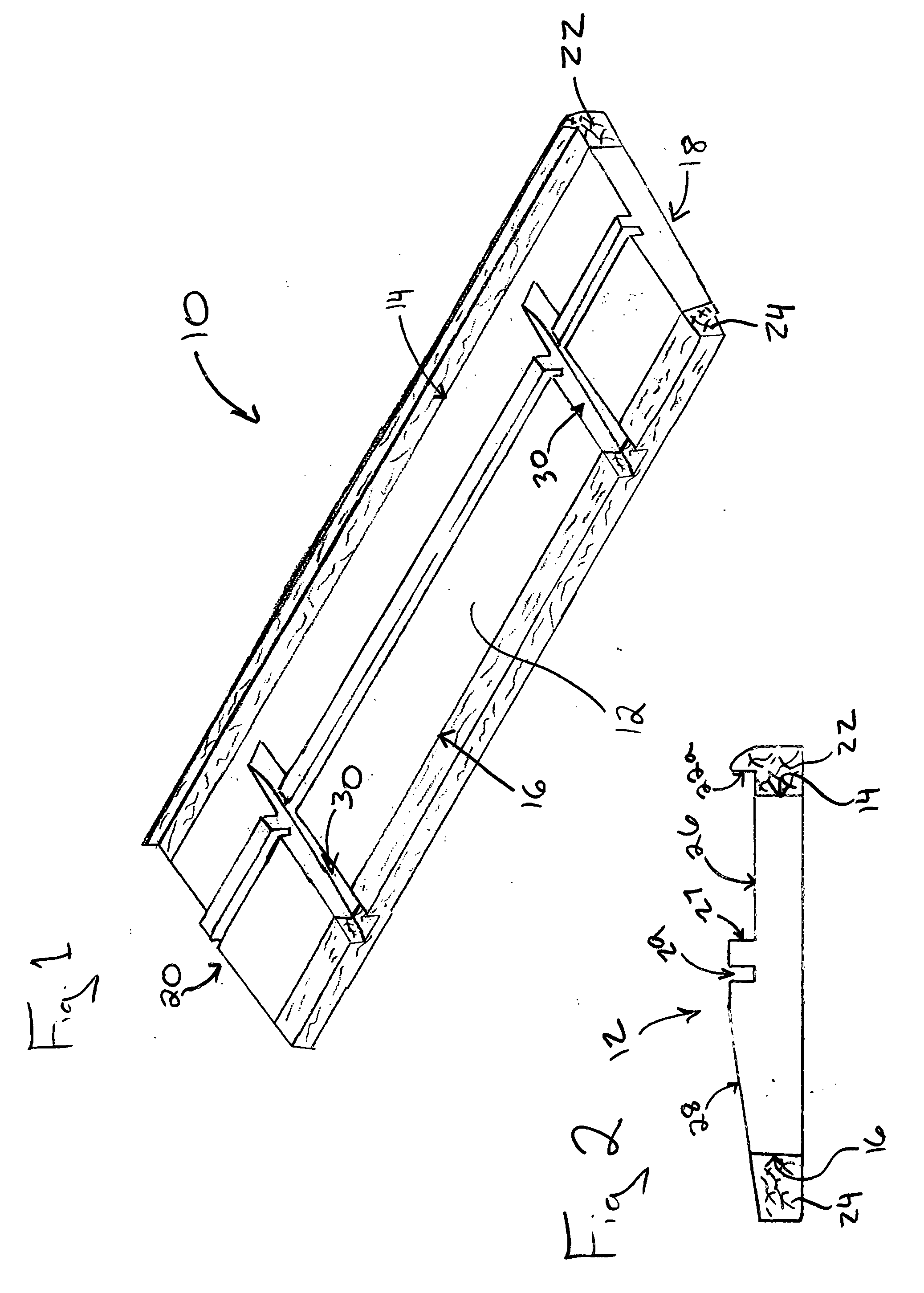
[0027] a doorsill assembly 70 is best shown in FIGS. 5 and 6. Similar to assembly 40, assembly 70 includes a base 72, a threshold member 74, and a cover panel 76. Base 72 is nearly identical to base 10. Accordingly, base includes central portion 12 with first and second strips 22, 24 secured thereto.

[0028] Threshold member 74 is similar to threshold member 42, but does not include a storm drain channel. Cover panel 76 has a slightly different configuration compared to cover panel 44, and includes an upwardly extending, interiorly disposed wall 76a which cooperates with a weather strip gasket 78 to seal the gap between cover panel 76 and threshold member 74, such as the weather strip gasket described in U.S. Pat. No. 6,484,446 to Young, the disclosure of which is incorporated herein by reference.

[0029] While the disclosed banded doorsill base 10 has been described in terms of various embodiments, it should be understood that base 10 (or 72) may be used for any doorsill assembly. Acc...


PUM


Abstract

The present invention is directed to a banded doorsill base for disposition between a pair of doorjambs of a door frame. The doorsill base includes an elongate central portion formed from a polymeric material having a first coefficient of linear expansion, and first and second wooden strips bonded to and extending along opposite sides of the central portion for constraining the central portion and preventing linear expansion thereof. The first and second strips are formed from a material having a second coefficient of linear expansion less than the first coefficient. The first and second strips substantially prevent linear expansion of the central portion. The present invention also relates to a method of forming the banded doorsill base, and to a doorsill assembly having a banded doorsill base.

Description

FIELD OF THE INVENTION [0001] The present invention is directed to a banded doorsill base for disposition between a pair of door jambs of a door frame. The doorsill base includes an elongate central portion formed from a polymeric material having a first coefficient of linear expansion, and first and second wooden strips bonded to and extending along opposite sides of the central portion for constraining the central portion and preventing linear expansion thereof. The first and second strips are formed from a material having a second coefficient of linear expansion less than the first coefficient. The first and second strips substantially prevent linear expansion of the central portion. The present invention also relates to a method of forming the banded doorsill base, and to a doorsill assembly having a banded doorsill base. BACKGROUND OF THE INVENTION [0002] Doorsill assemblies have been used for many years to seal the bottoms of swinging doors when they are in the closed position...

Claims


Application Information

Patent Timeline
Patent Type & Authority Applications(United States)
IPC IPC(8): E06B1/70
CPCE06B1/70E06B2001/707
Inventor YOUNG, ROBERT H.
Owner YOUNG ROBERT H
Why Eureka
Try Eureka