Perforating device
- Summary
- Abstract
- Description
- Claims
- Application Information
AI Technical Summary
Benefits of technology
Problems solved by technology
Method used
Image
Examples
Embodiment Construction
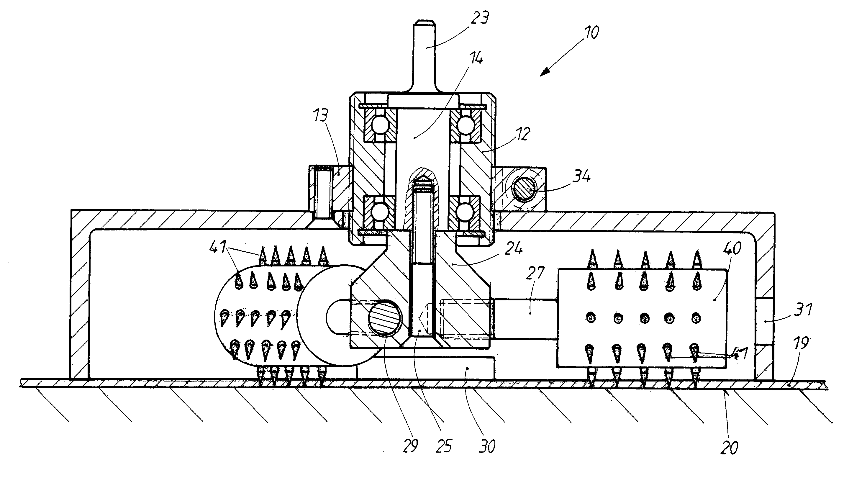
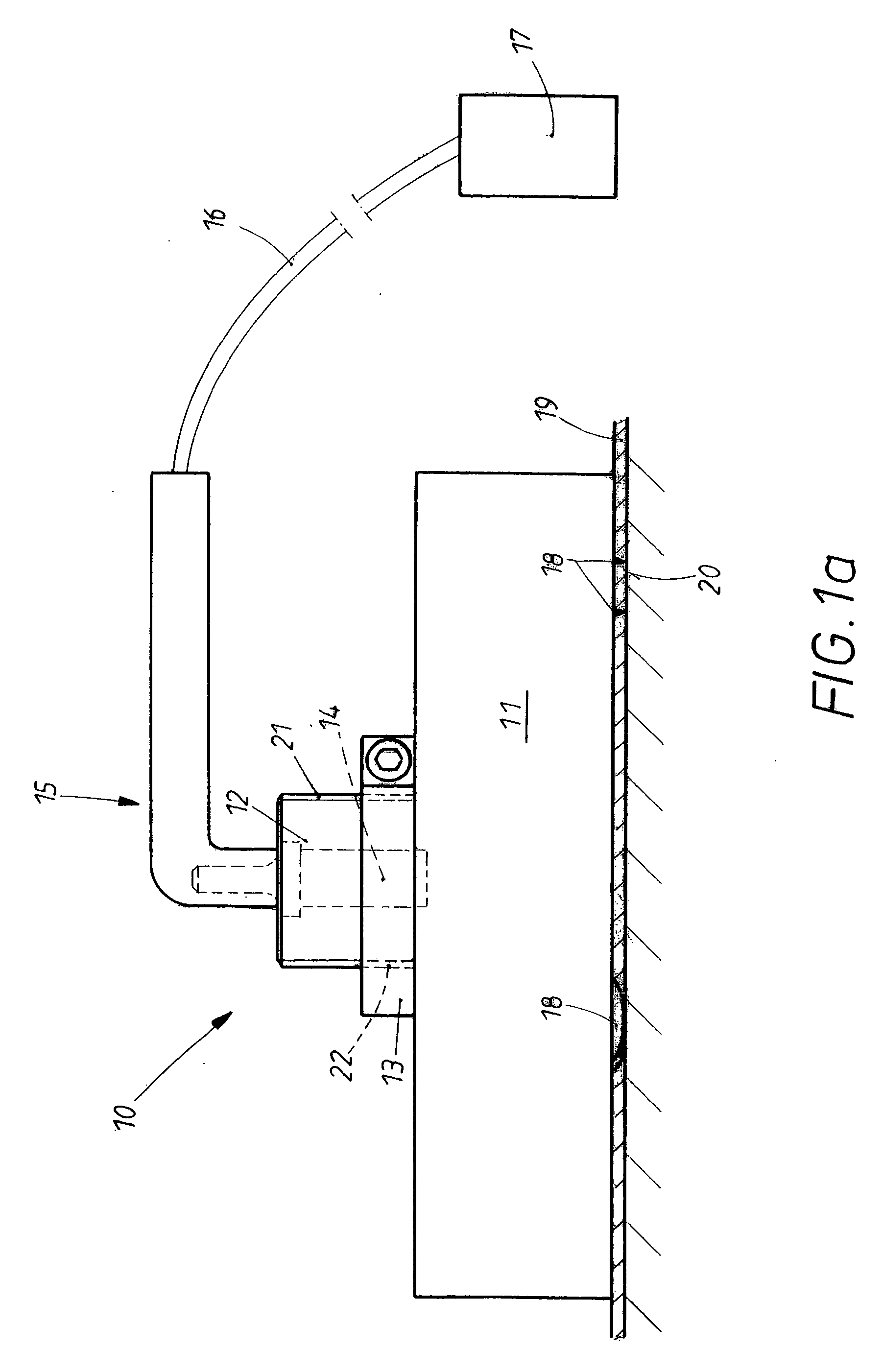
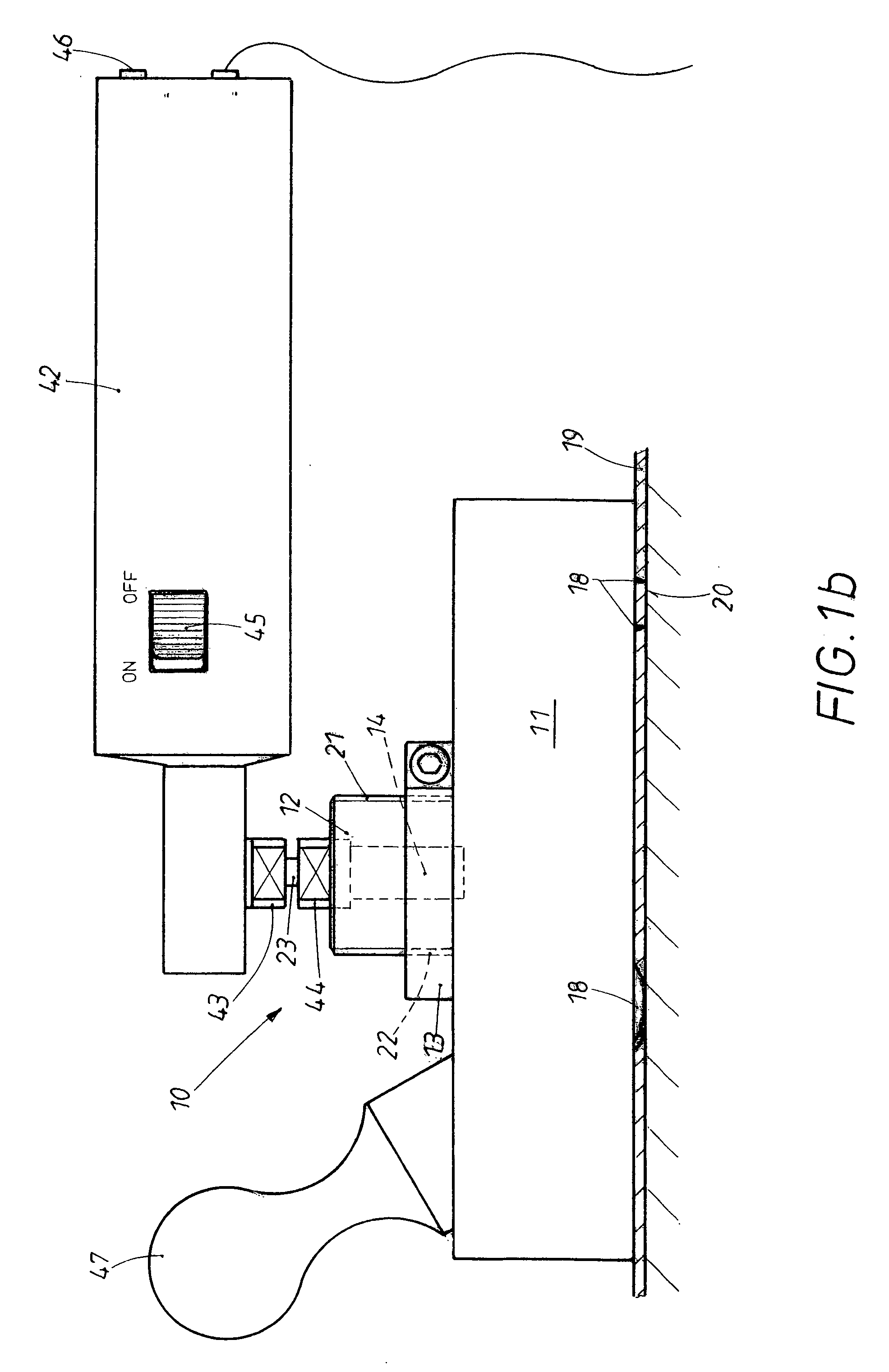
[0025] The perforating device 10 shown in FIG. 1a consists essentially of a protective part 11, from which an adjusting sleeve 12 projects. The sleeve carries a thread 21, which engages in the internal thread 22 of a clamping ring 13. The clamping ring 13 itself is held in place on the protective part 11 by a screwed joint. The end 23 of a rotating pintle 14 projects from the adjusting sleeve. A flexible shaft 16 is connected to the rotating pintle 23. The flexible shaft 16 passes through the handle 15.
[0026] The flexible shaft 16 leads to an electric drive motor 17, which can be connected to a battery or to line current. Here the flexible shaft is long enough, so that the operator can either hang the drive motor on his shoulder or carry it in a pocket.
[0027] Perforating tools 18 in the shape of circular blades project from the lower part of the hood-like protective part 11. These blades have spikes, which penetrate into the wallpaper 19 to be perforated, which is glued to a subst...
PUM
| Property | Measurement | Unit |
|---|---|---|
| Diameter | aaaaa | aaaaa |
| Distance | aaaaa | aaaaa |
| Circumference | aaaaa | aaaaa |
Abstract
Description
Claims
Application Information
 - R&D
- Intellectual Property
- Life Sciences
- Materials
- Tech Scout
- Unparalleled Data Quality
- Higher Quality Content
- 60% Fewer Hallucinations
Browse by: Latest US Patents, China's latest patents, Technical Efficacy Thesaurus, Application Domain, Technology Topic, Popular Technical Reports.
© 2025 PatSnap. All rights reserved.Legal|Privacy policy|Modern Slavery Act Transparency Statement|Sitemap|About US| Contact US: help@patsnap.com


