Swing cylinder

a technology of swinging cylinders and cylinders, which is applied in the field of swinging cylinders, can solve the problems of cylinders that may have problems, cylinders that are more or less unstable, and open guide slots at the end, so as to prevent contaminates, reduce costs, and be robust and durable.

Active Publication Date: 2006-08-10
DELAWARE CAPITAL FORMATION
View PDF8 Cites 25 Cited by
  • Summary
  • Abstract
  • Description
  • Claims
  • Application Information

AI Technical Summary

Benefits of technology

[0016] Still another object of the present invention is to provide a more robust and durable swing cylinder that is enclosed and will prevent contaminates from the manufacturing environment from entering and con

Problems solved by technology

The guide slot that is open at the end, however is more or less unstable to a certain extent because it can be spread apart more or less conically unless it is over diminished with regard to its wall thickness.
Many of these prior art swing cylinders may have problems with repeating the exact clamping forces at an exact position due to the play or wobble generally located in the swing cylinder components.
Furthermore, many of these prior art swing cylinders cannot hold with a force tha

Method used


Image

  • Swing cylinder
  • Swing cylinder
  • Swing cylinder

Examples


Embodiment Construction

)

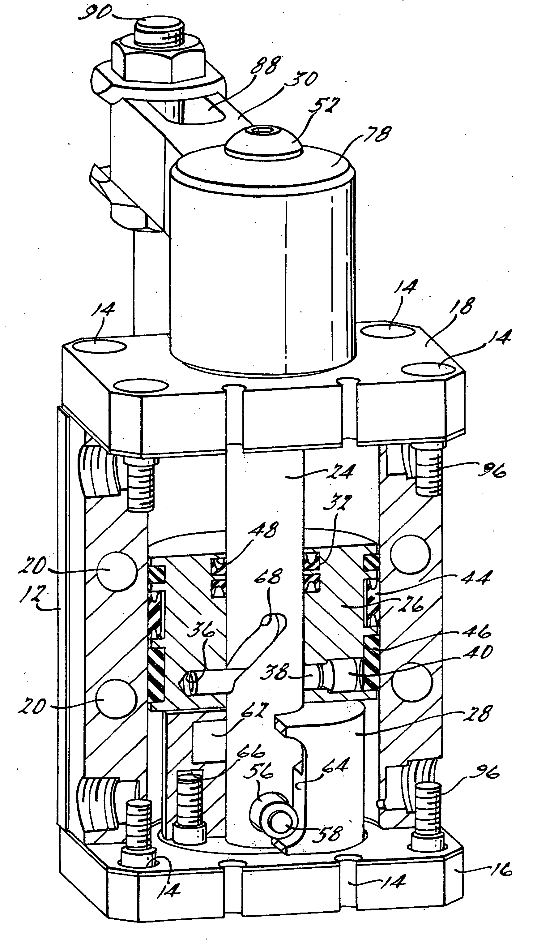
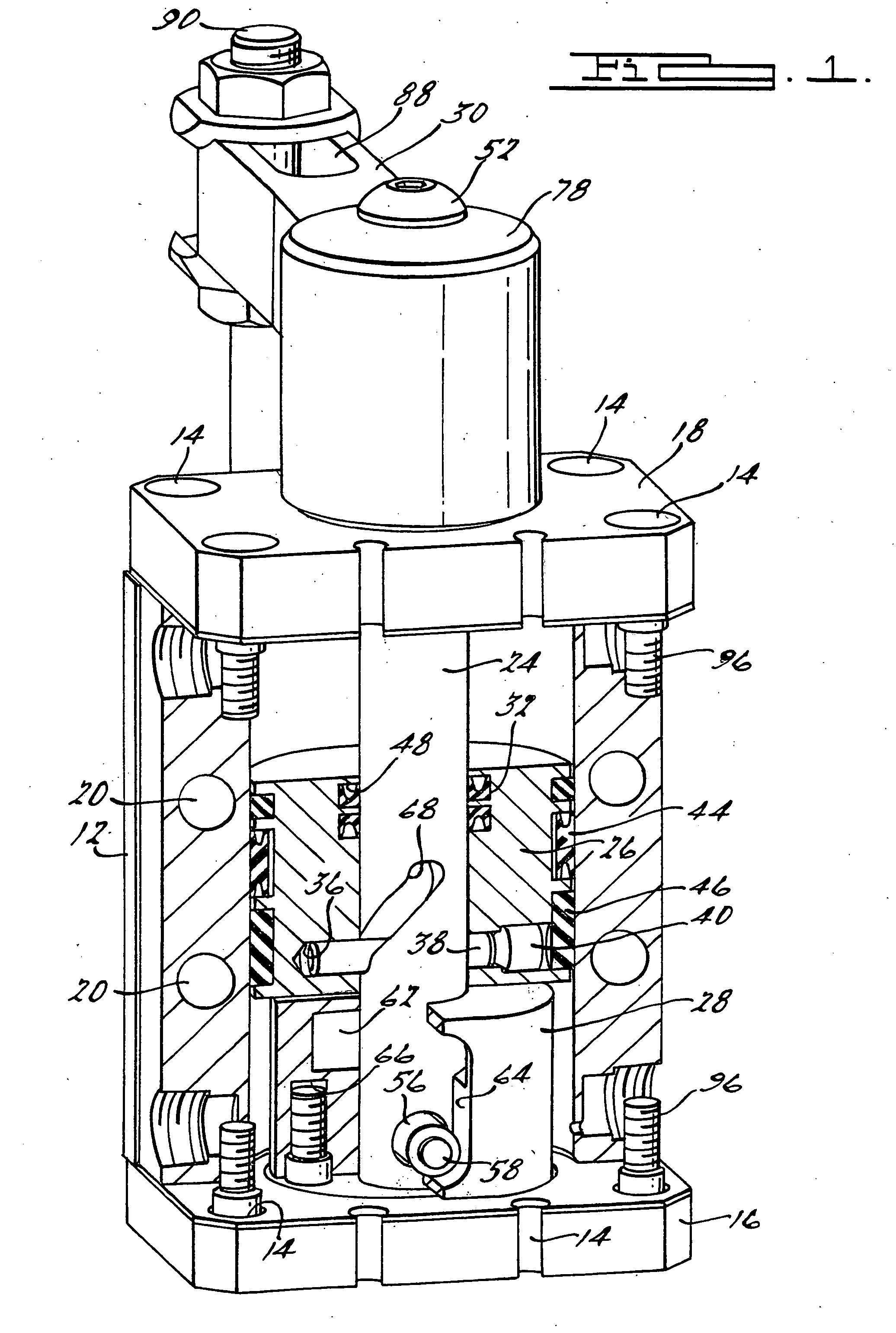
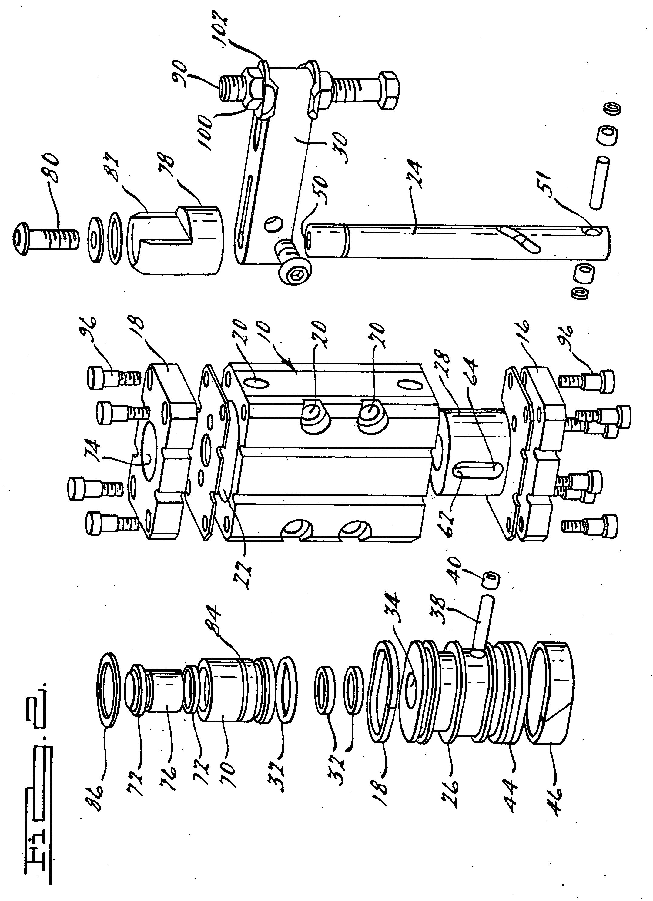
[0027] A swing cylinder 10 according to the present invention is shown in FIG. 1-3. The swing cylinder 10 will be for use in any number of manufacturing environments and will be capable of being sized from extremely small swing cylinders to extremely large swing cylinders to cover industries as vast as robotic industries for electronic components manufacture to holding automobile cars or the like as workpieces in an manufacturing environment. The flexibility of size and operation of the swing cylinder 10 is a key advantage of the present swing cylinder 10 over those of the prior art. As shown in the Figures, the swing cylinder 10 includes a body 12 that generally has a rectangular cross section. The body 12 includes a plurality of orifices 14 through an end thereof for use in securing an end cap 16 and a front cap 18 to respective sides thereof. The body 12 also includes a plurality of orifices 20 or cavities 20 therein some of which may be threaded for use in mounting the swing cy...


PUM


Abstract

A swing cylinder having a body and an end cap on each end of the body. The cylinder also has a piston arranged within the body. The cylinder has a rod engaged with the piston and has an arm attached to one end thereof. A guide is arranged on the opposite end of the rod. The guide is also attached to one of the end caps.

Description

[0001] This Application Claims the Benefit of Provisional Application Ser. No. 60 / 651,178 filed Feb. 8, 2005BACKGROUND OF THE INVENTION [0002] This invention will broadly relate to cylinders, and more particularly relate to a swing cylinder especially for holding workpieces. [0003] Swing cylinders and swing clamping devices are well known in the art. Generally, the cylinder is sealed on the end away from the clamping arm with a flange connecting plate, and a swinging guide sleeve for the piston rod, which has a relatively small diameter with respect to the inside diameter of the cylinder. The piston rod is secured only in and on a relatively short bore of the upper cylinder bottom which forms a unit with the cylinder. Apart from the fact that the cylinder is accessible only from its mounting side end, installation or removal of the piston rod with the piston and the guide sleeve are possible only from the mounting side of the cylinder. The swing guide slot for the piston must remain...

Claims


Application Information

Patent Timeline
IPC IPC(8): B23Q3/08F01B3/00
CPCB23Q3/069B23Q3/08B25B5/062F15B15/063
Inventor RENTZ, MATTHEW
Owner DELAWARE CAPITAL FORMATION
Why Eureka
Try Eureka