Apparatus and method for caring for obstructive sleep disorder breathing

Inactive Publication Date: 2006-08-10
SARKISIAN EDVARD
9 Cites 57 Cited by

AI-Extracted Technical Summary

Problems solved by technology

Usually, airway obstruction results from the apposition of the rear portion of the tongue or soft palate with the posterior pharyngeal wall.
Snoring occurs when the pharyngeal airway is partially obstructed, resulting in vibration of the oral tissues during respiration.
These sleep disorders tend to become more severe as patients grow older, likely due to a progressive loss of muscle tone in the patient's throat and oral tissues.
Problems and difficulties encountered with most conventional intra-oral appliances, including those taught by the U.S. Pat. Nos. 5,365,945, 6,041,784, and 6,161,542, all to Halstrom, stem from the use of multiplicity of parts and elements necessary to mount, connect, and use the appliance.
The conventional assemblies employ sidebars, clasps, wires, screw mechanisms, and many other parts that are complicated to assemble and require constant, professionally administered maintenance.
In addition, most of the conventional intra-oral appliances do not allow for different vertical settings, nor do they allow for lateral movem...

Benefits of technology

[0013] The present invention provides an intra-oral device for OSA and snoring patients that has few ...

Abstract

The present invention provides an adjustable connection mechanism 200 for releasabley coupling two components. The adjustable connection mechanism 200 comprises a first retention guide channel 202 coupled to a surface of a first component, a second retention guide channel 204 oriented substantially perpendicular to the first retention guide channel 202 and coupled to a surface of a second component that faces the surface of the first component, an adjuster 206 removabley inserted in the first retention guide channel 202, and an interlocking member 208 releasabley fastening the two retention guide channels 202 and 204.

Application Domain

Teeth fillingSnoring prevention +1

Technology Topic

Sleep disordered breathingEngineering +2

Image

  • Apparatus and method for caring for obstructive sleep disorder breathing
  • Apparatus and method for caring for obstructive sleep disorder breathing
  • Apparatus and method for caring for obstructive sleep disorder breathing

Examples

  • Experimental program(1)

Example

(1) Introduction
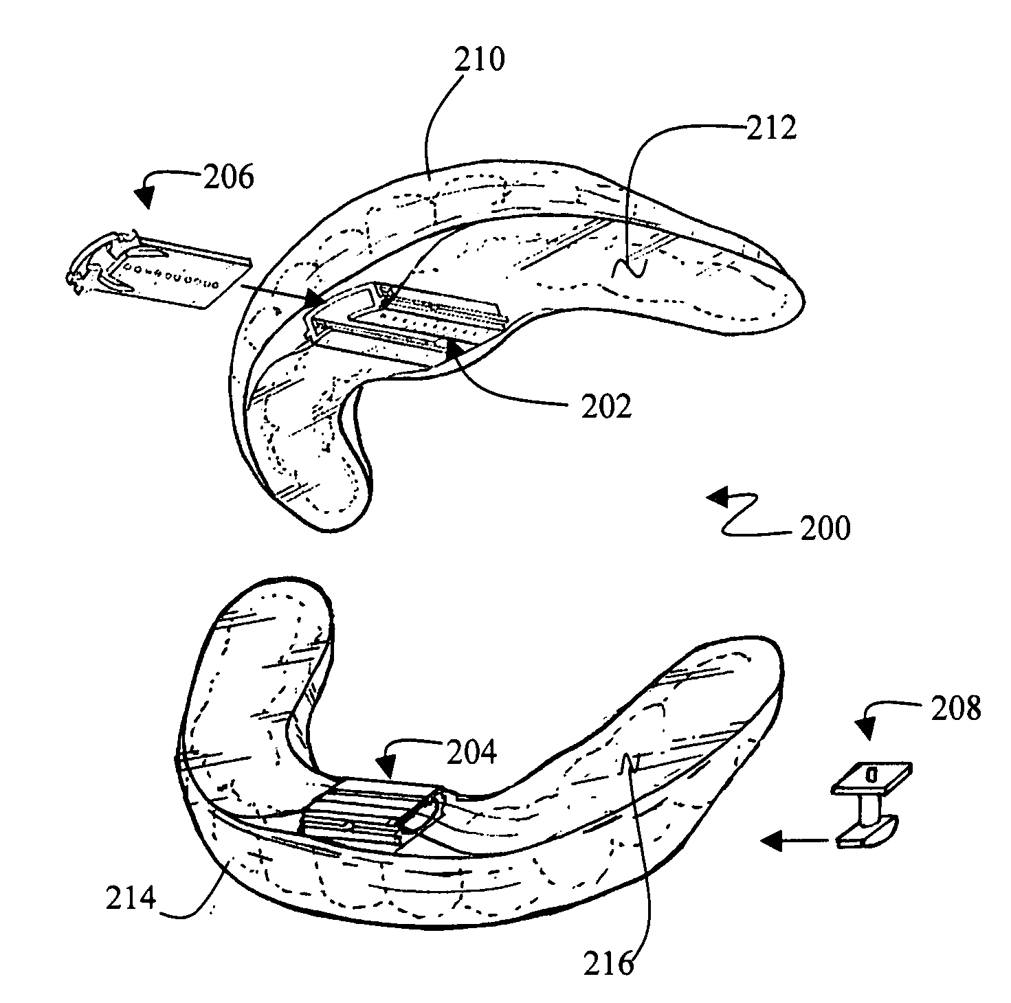
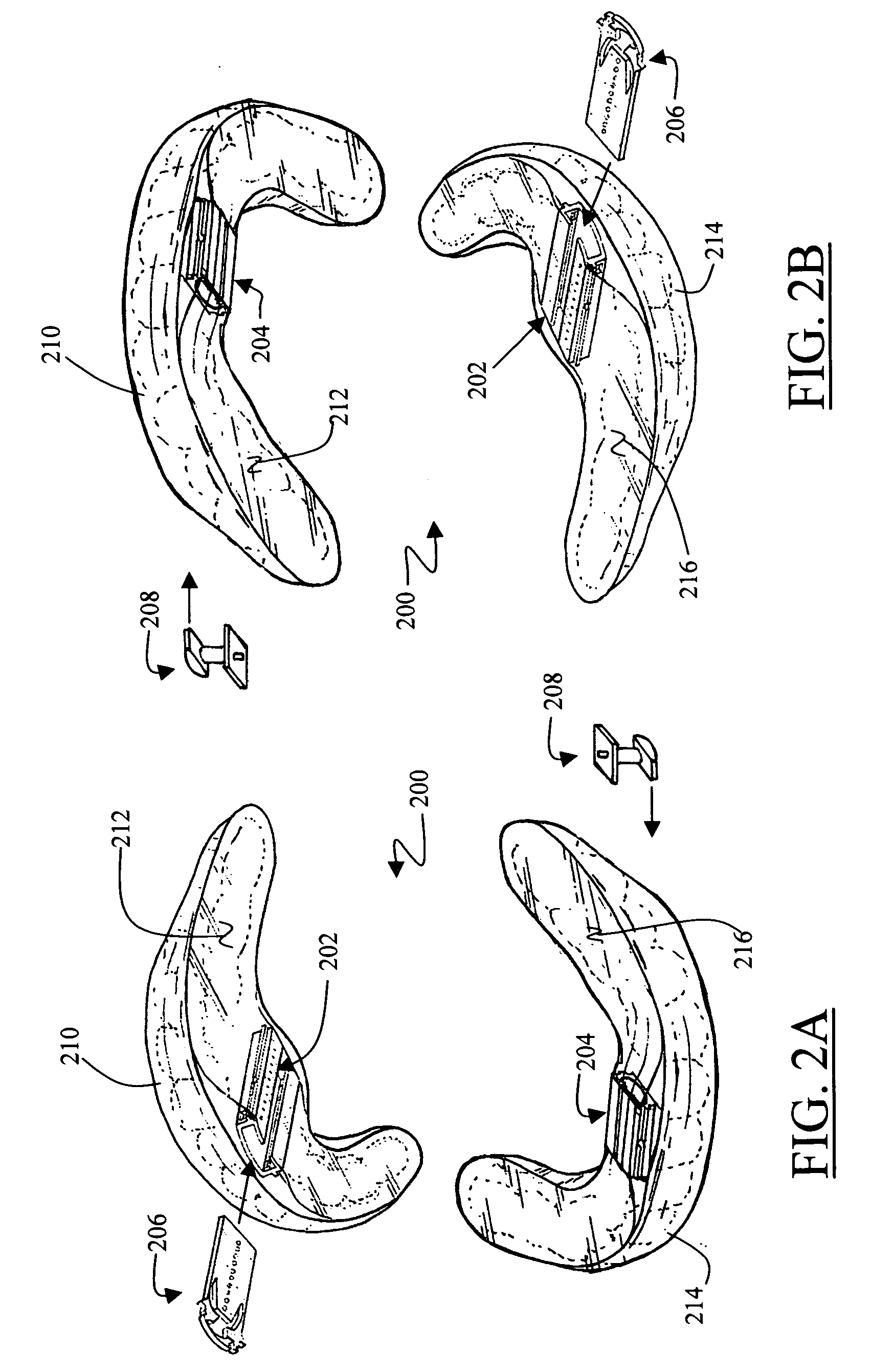
[0091] Most conventional connection mechanisms for intra-oral appliances are comprised of numerous, complex parts that require a professional to assemble and adjust. The present invention provides a simple, adjustable connection mechanism comprised of only four components that are easily assembled, and may be adjusted and used without the need for special tools or professionals.
[0092] Before providing details regarding the various aspects of the invention, first an overview of the present invention is provided, which describes the interconnections and operation of various major components in order to provide a more tangible understanding thereof without getting lost in the details. Next, an explicatory section is provided in which the various major components presented in the overview are described in detail.
(2) Overview
[0093]FIG. 2A illustrates a general overview of an intra-oral appliance in accordance with the present invention, including an adjustable connection mechanism 200 having a primary retention guide 202 that is coupled to a bottom surface 212 of a maxillary member 210, and a secondary retention guide 204 that is coupled to a bottom surface 216 of a mandibular member 214. As illustrated in FIG. 2B, the primary retention guide 202 may instead be coupled to the bottom surface 216 of the mandibular member 214, and the secondary retention guide 204 coupled to the bottom surface 212 of the maxillary member 210. Regardless of which member (210 or 214) the retention guides (202 and 204) are coupled with, the primary retention guide 202 should be aligned axial to the oral cavity, with the secondary retention guide 204 oriented substantially perpendicular to the primary retention guide 202.
[0094]FIGS. 2A and 2B further illustrate a mandibular adjuster 206 that is inserted into the primary retention guide 202, and used for facilitating an incremental movement of the mandible 118. An interlocking member 208 is inserted into the secondary retention guide 204 at one end, and the primary retention guide 202 at its other. The interlocking member 208 couples the maxillary member 210 and the mandibular member 214, and in connection with the mandibular adjuster 206, assists in the incremental movement of the mandible 118. FIG. 2C illustrates the fully assembled, adjustable connection mechanism 200 of FIG. 2A, with the maxillary member 210 and the mandibular member 214 in a coupled position.
[0095] In general, both the maxillary member 210 and the mandibular member 214 may be comprised of thermoplastic transparent material, which are processed by a laboratory technician for a custom fit for both oral arches when worn by a users. In particular, both the top and the bottom surfaces of the maxillary member 210 are customized in a well-known manner to conform to an individual's maxillary dentition, and the top and the bottom surfaces of the mandibular member 214 are customized in a well-known manner to conform to an individual's mandibular dentition.
[0096] As illustrated in FIGS. 3A to 3H, instead of using the laboratory fit customized maxillary member 210 and the mandibular member 214, the adjustable connection mechanism 200 may instead be coupled to a maxillary frame 310 and a mandibular frame 314. Instead of conforming (custom fitting) to an individual's maxillary or mandibular dentition, the frames include side walls 302, and are configured to the general form of a human oral arch, and come in three industry standard sizes of small, medium, and large. Those skilled in the art would recognize that the maxillary and the mandibular frames are identical in form. FIGS. 3E to 3H illustrate the top surfaces of both the maxillary frame 310 and the mandibular frame 314, including the side walls 302 that form the channels 320. As FIGS. 3G and 3H illustrate, the channels 320 are used for containing impression material 322 that can conform to the maxillary and the mandibular dentition, after curing. The impression material 322 may be comprised of a quick impression or a boil-and-fit material, both of which are well known, and cure at room temperature.
[0097] Referring back to FIGS. 3A and 3B, the primary retention guide 202 may be coupled to a bottom surface 312 of the maxillary frame 310, or the bottom surface 316 of the mandibular frame 314. FIGS. 3C and 3D illustrate the secondary retention guide 204 coupled to the bottom surface 312 of the maxillary frame 310, or the bottom surface 316 of the mandibular frame 314. As with custom fit maxillary member 210 or the mandibular member 214, regardless of which frame (310 or 314) the retention guides (202 and 204) are coupled with, the primary retention guide 202 should be aligned axial to the oral cavity, with the secondary retention guide 204 oriented substantially perpendicular to the primary retention guide 202.
(3) Explication
[0098] The following paragraphs describe in detail the various embodiments for the adjustable connection mechanism 200 of the present invention, including (A) the primary retention guide 202, (B) the secondary retention guide 204, (C) the mandibular adjuster 206, and finally (D) the interlock member 208. Different reference numbers are used for representing different embodiments of each individual component. However, when referring to the same component in a general manner, and not within the context of any particular embodiment, then the same reference number that has been used in the FIGS. 2A and 2B for each component will continue to be used throughout the remainder of the disclosure.
(A) Primary Retention Guide
[0099]FIGS. 4A to 4C illustrate the various embodiments for the primary retention guide 202 illustrated in FIGS. 2A and 2B, which may comprise of titanium alloy or thermoplastic material. One of the functions of the primary retention guide 202 is to contain the mandibular adjuster 206, and the anchor piece of the interlock member 208, and in relation to the secondary retention guide couple the lower and the upper jaws. In general, as illustrated in FIGS. 4A to 4C, all of the embodiments of the primary retention guide 202 are comprised of a bottom side 404 that is integral with and normal to two parallel primary retention guide walls 412 and 422. The primary retention guide 202 also includes an elongated primary retention guide open channel 410 that is defined by the bottom side 404, the two walls 412 and 422, and two opposing primary retention guide flanges 420 and 418 that are integral with and normal to the two walls 412 and 422, respectively. As illustrated, at least one primary retention guide flange top surface 420, exterior to the elongated channel 410 includes incremental indicators for gauging the incremental movement of the mandible to one of an anterior and a posterior positions. Although only ten incremental values are illustrated for clarity, finer incremental gauging values may also be used. The proximal ends of the primary retention guide walls 412 and 422 include two primary retention guide wall openings 408 and 406, respectively, for receiving a protruded piece (nubs 616 and 614 illustrated in FIGS. 6A to 6G) of the mandibular adjuster 206. The proximal end 402 of the primary retention guide is curved to conform to the oral arch.
[0100] In particular, the primary retention guide 400 illustrated in FIG. 4A is further comprised of primary retention guide side bars 414 and 424, which are integral with and are axially located along a middle of the primary retention guide walls 412 and 422, respectively, exterior to the elongated channel 410. Each of the side bars 414 and 424 are further comprised of at least one cutout section along the side bar length (only the cutout section 416 along the length of the side bar 414 is illustrated for clarity). The exterior surfaces of the primary retention guide 400, which includes the exterior of the bottom side 410, and the two walls 412 and 422, and up to and including the respective two side bars 414 and 424 may be enclosed within one of the maxillary member bottom surface 212 and the mandibular member bottom surface 216, allowing the channel 410 and the two side holes406 and 408 to remain open for removable insertion of the mandibular adjuster and the interlock member. The primary retention guide 400 may also be enclosed within one of the maxillary frame bottom surface 312 and the mandibular frame bottom surface 316 in similar manner. The cutout sections of the side bars 414 and 424 function to frictionally secure the primary retention guide 400 within the maxillary or the mandibular member or frame. That is, the cutout sections facilitate in preventing the anterior and posterior movements of the primary retention guide 400 within the maxillary or the mandibular member or frame.
[0101]FIG. 4B illustrates another embodiment of the primary retention guide 432 with at least two of a primary retention guide bottom side perimeters 428 and 430 extend beyond the primary retention guide walls 412 and 422, respectively. The two extended perimeters 428 and 430 are functionally equivalent to the side bars 414 and 424 illustrated in FIG. 4A. The extended perimeters 428 and 430 are further comprised of at least one cutout section along each of their lengths (only the cutout section 426 along the length of the extended perimeter 428 is illustrated for clarity). The exterior surfaces of the primary retention guide 432, which includes the exterior of the bottom side 410, the two extended perimeters 428 and 430, and parts of the two walls 412 and 422 may be enclosed within one of the maxillary member bottom surface 212 and the mandibular member bottom surface 216, allowing the channel 410 and the two side holes 406 and 408 to remain open for removable insertion of the mandibular adjuster and the interlock member. The primary retention guide 432 may also be enclosed within one of the maxillary frame bottom surface 312 and the mandibular frame bottom surface 316 in similar manner. FIG. 4C illustrates yet another embodiment of the primary retention guide 440 with a distal end wall 442 that may completely or partially close the distal end of the channel 410. It should be noted that although the distal end wall 442 is illustrated with the embodiment that includes extended bottom side perimeters 428 and 430, it would be obvious to those skilled in the art to also use the wall 442 with the primary retention guide 400, which is illustrated in FIG. 4A.
(B) Secondary Retention Guide
[0102]FIGS. 5A to 5F illustrate the various embodiments for the secondary retention guide 204 illustrated in FIGS. 2A and 2B, which may comprise of titanium alloy or thermoplastic material. One of the functions of the secondary retention guide 204 is to contain the headpiece of the interlock member 208, and in relation to the primary retention guide 202 couple the upper and lower jaws. In general, as illustrated in FIGS. 5A to 5F, all of the embodiments of the secondary retention guide 204 are comprised of a bottom side 516 that is integral with and normal to two secondary retention guide walls 510 and 511, and further include two opposing secondary retention guide flanges 514 and 512 that are integral with and normal to the walls 510 and 511, respectively. Although not illustrated, the distal end 513 of the secondary retention guide 204 may be completely or partially closed, similar to that of the primary retention guide 440, which is illustrated in FIG. 4C.
[0103] In particular, as illustrated in FIG. 5A, the secondary retention guide 500 is further comprised of an elongated secondary retention guide open channel 502 that is oval or round shaped, and is defined by the bottom side 516, the two walls 510 and 511, and two opposing flanges 514 and 512. As further illustrated, the walls 510 and 511 are further comprised of secondary retention guide side bars 504 and 506, respectively, which are integral with and are axially located along a middle of the respective walls 510 and 511, exterior to the oval channel 502. Each of the side bars 504 and 506 are further comprised of at least one cutout section along the side bar length (only the cutout section 508 along the length of the side bar 504 is illustrated for clarity). The exterior surfaces of the secondary retention guide 500, which includes the exterior of the bottom side 516, and the two walls 510 and 511, and up to and including the respective two side bars 504 and 506 may be enclosed within one of the maxillary member bottom surface 212 and the mandibular member bottom surface 216, allowing the channel 502 to remain open for removable insertion of the one end of the interlock member. The secondary retention guide 500 may also be enclosed within one of the maxillary frame bottom surface 312 and the mandibular frame bottom surface 316 in similar manner. The cutout sections of the side bars 504 and 506 frictionally secure the secondary retention guide 500 within the maxillary or the mandibular member or frame. That is, the cutout sections facilitate in preventing the lateral movement of the secondary retention guide 500 within the maxillary or the mandibular member or frame.
[0104]FIG. 5B illustrates another embodiment of the secondary retention guide 520 with at least two of a secondary retention guide bottom side perimeters 522 and 524 extend beyond the walls 510 and 511. The two extended perimeters 522 and 524 are functionally equivalent to the side bars 504 and 506 illustrated in FIG. 5A. The extended perimeters 522 and 524 are further comprised of at least one cutout section along each of their lengths (only the cutout section 526 along the length of the extended perimeter 522 is illustrated for clarity.) The exterior surfaces of the secondary retention guide 520, which includes the exterior of the bottom side 516, the two extended perimeters 522 and 524, and parts of the two walls 510 and 511 may be enclosed within one of the maxillary member bottom surface 212 and the mandibular member bottom surface 216, allowing the channel 502 to remain open for removable insertion of the one end of the interlock member. The secondary retention guide 520 may also be enclosed within one of the maxillary frame bottom surface 312 and the mandibular frame bottom surface 316 in similar manner.
[0105]FIG. 5C illustrates another embodiment of the secondary retention guide 530, which is similar to the secondary retention guide 500 illustrated in FIG. 5A, but with the difference of an elongated secondary retention guide open channel 532 that is semi-circularly shaped. FIG. 5D is similar to FIG. 5C, but without the side bars 504 and 506, and includes instead the two extended perimeters 522 and 524, with their respective cutout sections, similar to FIG. 5B.
[0106]FIG. 5E illustrates another embodiment of the secondary retention guide 550, which is similar to the secondary retention guides 500 and 530 illustrated in the respective FIGS. 5A and 5C, but with the difference of an elongated secondary retention guide open channel 552 that is rectangular or square shaped. FIG. 5F is similar to FIG. 5E, but without the side bars 504 and 506, and includes instead the two extended perimeters 522 and 524, with their respective cutout sections, similar to FIGS. 5B and 5D. Although not illustrated, it should be obvious to one of ordinary skilled that the secondary retention guide channel inner circumference may also be configured into other forms.
(C) Mandibular Adjuster
[0107]FIGS. 6A to 6E illustrate the various embodiments for the mandibular adjuster 206 illustrated in FIGS. 2A and 2B, all of which are comprised of titanium alloy. One of the functions of the mandibular adjuster 206 is to facilitate the means for an incremental movement of the mandible in the posterior and anterior positions. In particular, FIG. 6A illustrates a mandibular adjuster 600 comprised of a base 602 having at least one aperture 622 along an axial midsection 613. Due to the strength of the titanium alloy, the distances 603 between apertures 622 may be reduced to allow a closer alignment of the holes 622. The closer arrangement (or grouping) of the apertures 622 allows for a greater number of holes 622 to be used along the axial midsection 613 for a finer adjustment (positioning) of the mandible.
[0108] The adjuster 600 further includes a first flexible arm 609 and a second flexible arm 611 having respective first and second flexible arm distal ends 606 and 604, which are coupled to the base 602, and respective, free, first and second flexible arm proximal ends for allowing movement of both arms 609 and 611 inwardly, towards the midsection 613 of the base 602. The midsections 608 and 610 of the respective arms 609 and 611 are contoured to allow the movement of the arms. As illustrated, the distal ends 606 and 604 of the respective arms 609 and 611 are wider, and become narrower at a middle section 608 and 610, and again wider at proximal ends of the arms 609 and 611. The narrower midsections 608 and 610 allow the titanium alloy composed arms to be flexible and to continue to maintain their original structure when at rest. The thickness of the arms 609 and 611 at the midsections 608 and 610 depend on the lengths of the arms desired. The use of longer arms may require the use of wider midsections 608 and 610 for maintaining the original structure (or shape) of the arms when at rest. The opposite is also true in that the use of shorter arms may require the use of narrower midsections 608 and 610 for better flexibility.
[0109] Both the first and the second arms 609 and 611 further include respective nubs 616 and 614, protruded for engaging the primary retention guide wall apertures 408 and 406 for removabley securing the mandibular adjuster 600 to the primary retention guide 202. The arms 609 and 611 further include respective tabs 618 and 620, which are used for griping and for moving the arms 609 and 611 inwardly towards the midsection 613 of the mandibular adjuster 600, in the directions indicated by the arrows A and B, for allowing insertion and removal of the mandibular adjuster 600 within the primary retention guide 202.
[0110]FIGS. 6B and 6C illustrate another embodiment of the mandibular adjuster 206. The mandibular adjuster 630 illustrated in FIGS. 6B and 6C includes a mandibular adjuster safety lock handle 632 having a safety handle proximal end 631 integral with the second flexible arm proximal end 611, and further has a free safety handle distal end 633. The free safety handle distal end 633 includes a tab 634 to allow a user to grasp the safety handle 632 and extend it away from the base 602, in the direction indicated by the arrow C. The free safety handle distal end 633 allows the inward movement of both the first and the second flexible arms 609 and 611 towards the midsection 613, indicated by the arrows D and E, when the distal end 633 is at an extended, open position (illustrated in FIG. 6C). On the other hand, as illustrated in FIG. 6B, the free distal end 633 will block the inward movement of both the first and second flexible arms 609 and 611 towards the midsection 613 when the distal end 633 is at a rest position. Although the safety lock handle 632 is illustrated and described as being integral with the second flexible arm proximal end, it should be obvious to those skilled in the art that the safety lock handle 632 may instead easily be made integral with the first flexible arm proximal end.
[0111]FIGS. 6D and 6E illustrate yet another embodiment of the mandibular adjuster 206, with FIG. 6D illustrating an unassembled adjuster 640 and FIG. 6E illustrating the assembled adjuster 640. The mandibular adjuster 640 uses titanium alloy wire 650 and titanium alloy spring 668 for the connection and movement of the adjuster arms 609 and 611. The mandibular adjuster 640 is comprised of base 602 that includes a distal 643, middle 645, and proximal 647 sections. The middle section 645 of base 602 includes a support hole 646, which is made perpendicular to the axial midsection 613, for inserting the support wire 650 through, as illustrated. The middle section 645 further includes two cylindrically concave female receiving couplers 644 and 642 for receiving the distal ends 658 and 656 of the respective two arms 609 and 611. The distal ends 658 and 656 are comprised of cylindrical male couplers for frictionally mating the two respective female receiving couplers 644 and 646. The arm distal end male couplers 658 and 656 further include respective cutout sections 654 and 652 for forming a passage for allowing the support wire 650 to pass through, thereby preventing a disjoining of the arms 609 and 611 from the base 602 when assembled. The proximal section 647 of the base 602 includes a midsection hole 659, which is made perpendicular to the axial midsection 613 for inserting a titanium alloy spring wire 668 through. The proximal ends of the two arms 609 and 611 include respective two apertures 666 and 664 for receiving the free ends of the spring wire 668 for a connection, as illustrated. As with the other mandibular adjuster embodiments of the present invention, the axial midsection 613 of adjuster 640 also includes at least one aperture 622 for positioning the mandible.
[0112] The spring wire connection and the frictionally coupled arm distal ends allow for the movement of the two arms 609 and 611 inwardly towards the midsection 613 in the directions indicated by the arrows F and G, illustrated in FIG. 6E. Tabs 618 and 620 are used for griping the arms 609 and 611 for movement, allowing for the insertion and removal of the adjuster 640 within the primary retention guide 202. The nubs 616 and 614 are used for engaging the mandibular adjuster 640 with the primary retention guide wall openings 406 and 408 for removabley securing the adjuster 640 within the primary retention guide. As illustrated in FIGS. 6F and 6G, when the adjuster 206 is inserted into the primary retention guide 202, the two protrusions or nubs 616 and 614 located at a proximal end of the adjuster 206 snap (or lock) into the two openings 406 and 408 located at a proximal end of the primary retention guide 202.
[0113] Although the nubs 616 and 614 of the mandibular adjuster 600 illustrated in FIG. 6A, and the mandibular adjuster 640 illustrated in FIGS. 6D and 6E can be used to removably secure the adjusters to the primary retention guide as described above, an optional safety cap illustrated in FIGS. 7A and 7B may also be used as an added security to further secure these mandibular adjusters within the primary retention guide. As illustrated in FIG. 7A and 7B, the safety cap 710, which is comprised of thermoplastic material, includes protrusions 712 and 708 that mate with respective tabs 618 and 620 of the mandibular adjusters 600 and 640. The distal end 702 of the safety cap 710 abuts the axial midsection 613 of the adjusters 600 and 640, with the two sides 724 and 722 of the safety cap 710 contacting the proximal ends of the respective arms 609 and 611 of the adjusters. The safety cap 710 further includes a safety cap string 720 that may be placed around the interlocking member 208.
(D) Interlock Member
[0114]FIGS. 8A to 8F illustrate the various embodiments for the interlock member 208 illustrated in FIGS. 2A and 2B, which are single piece units, integrally comprise of titanium alloy (FIGS. 8A to 8C) or thermoplastic material (FIGS. 8D to 8F). In general, the interlock member 208 functions to couple the primary retention guide 202 to the secondary retention guide 204, and in relation to the mandibular adjuster 206 facilitates in the incremental movement of the mandible in both the anterior and posterior positions, as well as vertical and lateral movements.
[0115] As illustrated in FIGS. 8A to 8C, the interlocking member 208 has a pin 802 for removable insertion in an at least one mandibular adjuster aperture 622. The interlocking member 208 further includes the anchor piece 804 for removable insertion into the primary retention guide 202, and a head for removable insertion into the secondary retention guide 204. The anchor piece 804 of the interlocking member 208 is coupled to the pin 802 and a first end of an interlocking member support 806, with the interlocking member support 806 comprised of a cylinder, as illustrated. The anchor piece 804 is in general rectangular, and its widths (shorter sides) are configured for insertion into the primary retention guide. That is, the anchor piece 804 is inserted with its widths normal to the axial length of the primary retention guide channel 410, and its lengths (the longer sides) held in parallel to the channel walls 412 and 422. This arrangement abuts the lengths of the anchor piece parallel against the inner channel walls 412 and 422 to prevent the interlock member to move or rotate within the primary retention guide. Accordingly, the anchor piece 804 (and the pin 802) are used for securing the interlock member in the primary retention guide.
[0116] The interlock member support 806 is available in three fixed, different height and width (diameter) sizes to facilitate varying vertical and lateral movement of the mandible for a more comfortable fit. The three different cylindrical configuration of the support 806 allows room for the secondary retention guide inner channel to move (or rotate) around the support 806 to a limited extent for lateral movement of the mandible, and its three different heights enables three varying vertical distances between the maxilla and the mandible. The cylindrical support also aids in the insertion of the interlock member into the secondary retention guide. Therefore, the three different cylindrical configuration of the support 806 allow for a vertical as well as lateral movement of the mandible. The head of the interlocking member 208 is coupled to a second end of the interlocking member support 806, with an outer form of the head configured as one of a round or oval 808, semi-circular 816, or square or rectangular 820 forms as illustrated in the respective FIGS. 8A, 8B, and 8C for the respective interlock members 801, 803, and 805.
[0117]FIGS. 8D to 8F illustrate another set of embodiments for the interlock member 208, all of which are comprised of thermoplastic material. To ensure appropriate strength and impact characteristics against pressures exerted by the lower and upper jaws, the interlocking member support of these embodiments is comprised of an upper cylinder section 806, and a lower trapezoidal pyramid section 830. The pyramidal section 830 provides a wider base for the interlock member support to improve its strength and impact characteristics. In addition, in these embodiments, two pins 836 and 834 are used that can divide the exerted forces of the lower and upper jaws to prevent the breakage of the thermoplastic pins. As with the embodiments illustrated in FIGS. 8A to 8C, the head of the interlocking member 208 of these embodiments is coupled to a second end of the interlocking member support 806, with an outer form of the head configured as one of a round or oval 808, semi-circular 816, or square or rectangular 820 forms as illustrated in the respective FIGS. 8D, 8E, and 8F for the respective interlock members 807, 809, and 811.
[0118]FIGS. 9A to 9G illustrate a sectional view of the primary retention guide 202 and the interlock member 208 as used in FIGS. 2A and 2C, as taken in the direction of arrows 9-9 of FIG. 2C. In particular, FIG. 9A illustrates the primary retention guide 432 axially coupled to the oral cavity to a maxillary member 210, and a secondary retention guide 550 coupled to the mandibular member 214, with the secondary retention guide 550 oriented substantially perpendicular to the primary retention guide 432. Further illustrated is the mandibular adjuster 630, which is removably inserted into the primary retention guide 432 for incremental movement of the mandible to one of posterior and anterior positions indicated by the arrow 903. The illustrated interlocking member 803 includes a pin 802 for removable insertion in an at least one mandibular adjuster aperture 622. The interlock member 803 further includes the anchor piece 804 for removable insertion into the primary retention guide 432, and a head 816 for removable insertion into the secondary retention guide 550 to interlock the primary retention guide 432 with the secondary retention guide 550, and facilitate in moving the mandible to one of an anterior and posterior positions. In addition, vertical and lateral movements of the mandible (indicated by arrow 902) are also possible because the interlock member support comes in three different height and width (diameter) sizes.
[0119]FIGS. 9B to 9G illustrate the same sectional view as illustrated in FIG. 9A, except that these figures illustrate the use of different embodiments of the various components of the connection mechanism 200. In general, FIGS. 9B to 9D illustrate the use of titanium composed interlock members with a single pin 802, which were illustrated in FIGS. 8A to 8C, and FIGS. 9E to 9G illustrate the use of thermoplastic composed interlock members with dual pins 836 and 834, which were illustrated in FIGS. 8D to 8E. In addition, FIGS. 9B to 9G use the particular embodiments of the secondary primary retention guide that were illustrated in FIGS. 5A, 5C, and 5E that include side bars 504 and 506, rather than the ones that have extended perimeters 522 and 524, such as that illustrated in FIG. 9A.
[0120] Although the invention has been described in language specific to structural features and or methodological steps, it is to be understood that the invention defined in the appended claims is not necessarily limited to the specific features or steps described. Rather, the specific features and steps are disclosed as preferred forms of implementing the claimed invention. Therefore, while illustrative embodiments of the invention have been described, numerous variations and alternative embodiments will occur to those skilled in the art. For example, the size of the adjuster mechanism and the number of apertures thereon may be varied. The forms of the primary and secondary retention guide channels (the inner circumference) may be varied, including the form of the head for the interlock member. The thermoplastic material mentioned in the explicatory section of the detailed description of the invention may comprise of polyketones, the non-limiting examples of which may include polyaryletherketones (PEK), which are repeating ether and ketone groups combined by phenly rings, polyetheretherketones (PEEK), which are repeating monomers of two ether groups and ketone group, and polyetherketoneketones (PEKK), which are repeating monomers of one ether group and two ketone groups. In addition, other materials with various combinations of the ether and ketone groups may be designed and used, the non-limiting combination example of which may include poly [ether] [ketone] [ether] [ketone] [ketone]. In fact, any material, including ceramics, which can provide excellent flexure, impact, and tensile characteristics appropriate for use within the oral cavity environment, may be used. That is, approved material having the appropriate characteristics to withstand the pressures exerted by the upper and lower jaws, as well as the existing environmental conditions of the oral cavity may be used for the primary retention guide, the secondary retention guide, the interlock member, and the optional safety cap. The primary retention guide, the secondary retention guide, the interlock member, and the optional safety cap need not be made from the same material. Such variations and alternate embodiments are contemplated, and can be made without departing from the spirit and scope of the invention.

PUM

no PUM

Description & Claims & Application Information

We can also present the details of the Description, Claims and Application information to help users get a comprehensive understanding of the technical details of the patent, such as background art, summary of invention, brief description of drawings, description of embodiments, and other original content. On the other hand, users can also determine the specific scope of protection of the technology through the list of claims; as well as understand the changes in the life cycle of the technology with the presentation of the patent timeline. Login to view more.

Similar technology patents

System and method for unified torque transmission and rotary sealing

ActiveUS20150107406A1few part
Owner:GE GLOBAL SOURCING LLC

Ice fishing reel

InactiveUS8480021B1few part
Owner:SAUK STEVEN A

Pullbox assembly

InactiveUS6881899B1easily assembleeasily attach and remove
Owner:TRANGSRUD JULIAN P

Firearm

ActiveUS20200200495A1reduce it susceptibility to malfunctionfew part
Owner:WEILHARTER RENE

Electric Actuator

InactiveUS20080129133A1easily assemble
Owner:DANAHER MOTION STOCKHOLM AB

Hydraulic relief valve

InactiveUS20070056632A1easily assemblemake up function be improve
Owner:VOLVO CONSTR EQUIP

Composite optical film

InactiveUS20100086743A1light efficiency be enhanceeasily assemble
Owner:ETERNAL MATERIALS CO LTD

Fluid sensing device

InactiveUS20190234775A1easy productionfew part
Owner:GUANGZHOU SEAGULL KITCHEN & BATH PROD

Connector for electrical wire-carrying conduits

InactiveUS7793988B1easily assemble
Owner:ATKORE STEEL COMPONENTS INC

Classification and recommendation of technical efficacy words

  • few part
  • easily assemble

System and method for unified torque transmission and rotary sealing

ActiveUS20150107406A1few part
Owner:GE GLOBAL SOURCING LLC

Ice fishing reel

InactiveUS8480021B1few part
Owner:SAUK STEVEN A

Firearm

ActiveUS20200200495A1reduce it susceptibility to malfunctionfew part
Owner:WEILHARTER RENE

Fluid sensing device

InactiveUS20190234775A1easy productionfew part
Owner:GUANGZHOU SEAGULL KITCHEN & BATH PROD

Adaptor for reducing EMI

InactiveUS20050111796A1easily assemblereduce aperture
Owner:MOLEX INC

Capacitive Sensor and Method and Apparatus for Controlling a Pump Using Same

ActiveUS20080229819A1easily assemblereduce cost associate with assembly and/or material cost
Owner:WAYNESCOTT FETZER

Quick pipe connector

Owner:YANG RICHARD

Component carrier

InactiveUS6995983B1less susceptibleeasily assemble
Owner:X2Y ATTENUATORS L L C

Collapsible pet housing

InactiveUS20050229866A1easily assembleeasy to clean
Owner:SIMPSON JEFFREY M
Why Eureka
Try Eureka