Housing bell with integrated pressure accumulator having a flanged cover

Active Publication Date: 2014-02-20
SCHAEFFLER TECH AG & CO KG
View PDF10 Cites 1 Cited by
  • Summary
  • Abstract
  • Description
  • Claims
  • Application Information

AI Technical Summary

Benefits of technology

[0007]It is an object of the present invention to reduce the costs associated with a pressure accumulator, to

Problems solved by technology

Moreover, screwed connections have a detrimenta

Method used


Image

  • Housing bell with integrated pressure accumulator having a flanged cover
  • Housing bell with integrated pressure accumulator having a flanged cover
  • Housing bell with integrated pressure accumulator having a flanged cover

Examples


Example

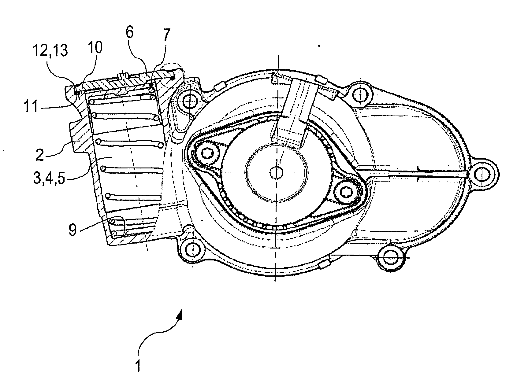
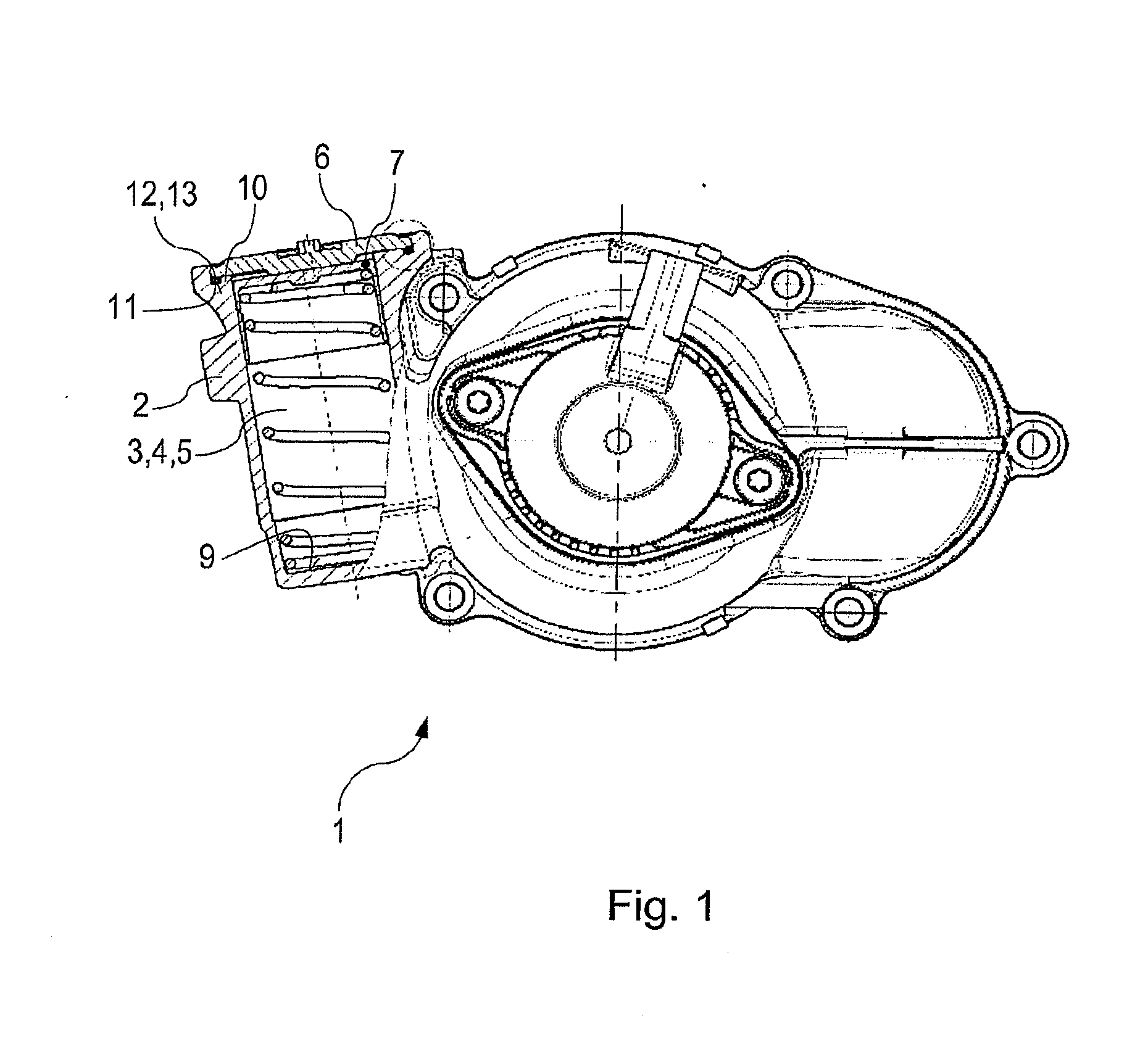
[0027]FIG. 1 shows a first embodiment of a pressure accumulator 1 according to the invention. The pressure accumulator 1 is part of a camshaft phaser which, in turn, is part of an internal combustion engine. The pressure accumulator 1 has a housing 2 that forms a cavity 3 in the form of a hole 4, especially in the form of a blind hole 5. The cavity 3 is closed with a cover 6.

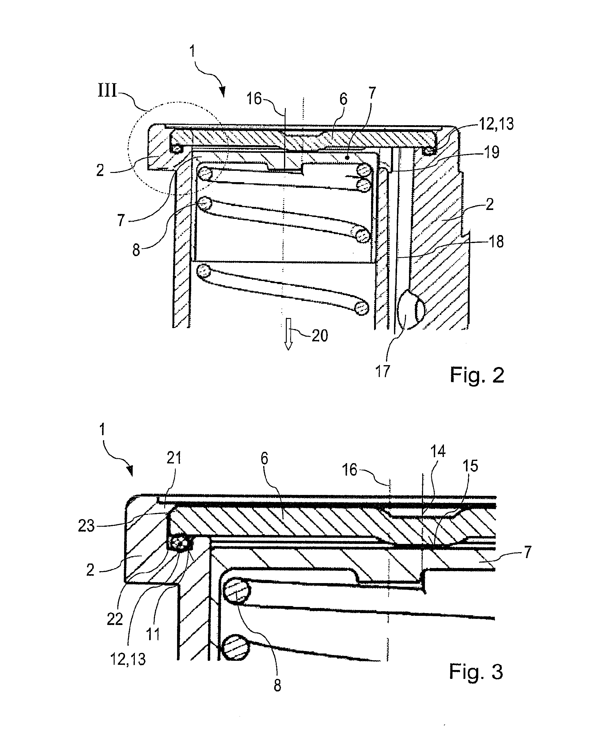
[0028]At the end of the cavity 3 on the cover side, there is a piston 7 which is mounted movably and in contact with a spring 8. The spring 8 is supported on the inside of the piston 7 and on the bottom 9 of the cavity 3. The cover 6 rests on a shoulder 10 of the housing, whereby a groove 11 is created between the housing 2 and the cover 6, and a sealing element 12, namely, an O-ring 13, is inserted into said groove 11.

[0029]The cover 6 has a centering bushing 14 and a piston stop 15 on the opposite side. This can be seen particularly well in FIG. 3.

[0030]FIGS. 1 to 3 also depict the longitudinal axis 4 of the h...


PUM

PropertyMeasurementUnit
Pressureaaaaaaaaaa
Circumferenceaaaaaaaaaa

Abstract

A pressure accumulator for a camshaft phaser of an internal combustion engine, including a housing that accommodates a piston and forms a cavity fillable with a hydraulic fluid. The cavity is configured as a hole and is closed by a cover on at least one side so as to be fluid-tight, whereby the cover is fastened to the housing by a flanged connection. A method for the production of a pressure accumulator for a camshaft phaser, including a pressure accumulator that forms a cavity, whereby a piston is placed into the cavity, and subsequently, a cover is put in place over the cavity—sealing it off towards the outside—in such a way that a material portion of the housing or of the cover creates such a positive connection between the cover and the housing that the cover is affixed in its position relative to the housing.

Description

[0001]The invention relates to a pressure accumulator for a camshaft phaser of an internal combustion engine, comprising a housing that accommodates a piston and that forms a cavity that can be filled with a hydraulic fluid, such as oil, whereby the cavity is configured as a hole and is closed by a cover on at least one side so as to be fluid-tight.BACKGROUND[0002]The state of the art discloses camshaft phasers that are employed in internal combustion engines of motor vehicles such as passenger cars or trucks. Such camshaft phasers serve to adjust the ignition timing of the internal combustion engine.[0003]German patent application DE 10 2010 012 917 A1 discloses such a camshaft phaser. This publication especially discloses a camshaft phaser for changing the angular position of a camshaft relative to a crankshaft of an internal combustion engine, whereby the camshaft phaser comprises an actuator and involves the actuation of a hydraulic valve, whereby the actuator is fastened to a h...

Claims


Application Information

Patent Timeline
IPC IPC(8): F01L1/344F01L1/047
CPCF01L1/047F01L1/3442F01L1/46F01L2001/34446Y10T29/49826
Inventor HOPPE, JENSBAYRAKDAR, ALIMEISBORN, MARCO
Owner SCHAEFFLER TECH AG & CO KG
Why Eureka
Try Eureka