Tank outlet fitting with flange

a technology of outlet fittings and fittings, which is applied in the direction of pipes, pipes/joints/fittings, packaging, etc., can solve the problem of adding significant costs to this necessary means

Inactive Publication Date: 2006-08-10
PISHOCK CHARLES T JR
View PDF33 Cites 1 Cited by
  • Summary
  • Abstract
  • Description
  • Claims
  • Application Information

AI Technical Summary

Benefits of technology

[0010] Accordingly, here is proved an integral fitting for a liquid retention tank adapted for sealing engagement with a tank outflow orifice normally provided in a tank lower wall comprising: (a) a generally tubular, rigid conduit means dimensioned to allow flow of viscous fluids therethrough, said conduit means having a first diameter; (b) an externally threaded, first segment abutting the first longitudinal end of the conduit means, with such threading adapted for an interruptible locking engagement with a separate drain line; (c) a hollow core and flanged second segment integral with the second longitudinal end of the conduit means, the flange of the second se

Problems solved by technology

To effect this tank outlet orifice and the transport hose interlinking, such requires the sizing and machining of three meta

Method used


Image

  • Tank outlet fitting with flange
  • Tank outlet fitting with flange
  • Tank outlet fitting with flange

Examples


Embodiment Construction

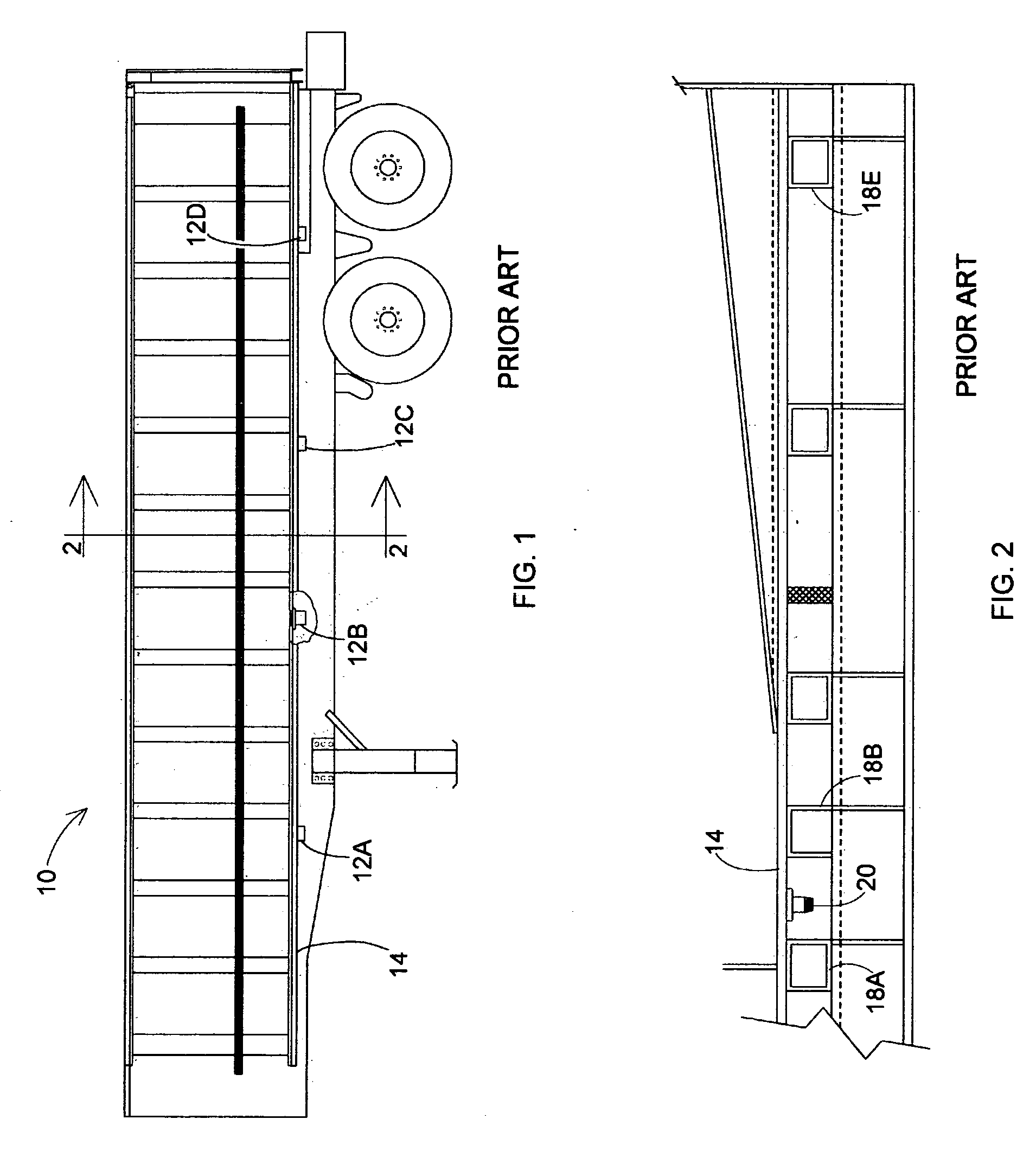
[0020] Referring now to the drawing, and to FIG. 1 in particular, there is depicted the trailer component 10 of a standard tractor trailer rig, used for over the road liquid transport. The static trailer 10, depicts three sites, along the bottom wall 14, at which such sites, outflow orifices, 12A, B, and C, are functionally positioned. It is within the skill of the art of trailer building, to provide as many such tank bottom outlets as the customer requires. The fitting is useful with any cargo of fluidized nature, which can by gravity also, dump its contents via an outlet hose connected thereto (not shown). As indicated, dependent on the capacity and cargo viscosity, there may be a number of outlet ports on the tank using the present invention.

[0021] In the broken away, vertical sectional view of FIG. 2, the bottom wall 14 of an elongate trailer is seen, also being provided with underlying, five hollow transverse beams, 18 A, B, C, D, and E, which beams bolster trailer bottom wall...


PUM


Abstract

An integral metallic fitting for affixing to a liquid retention tank orifice that serves to drain the tank as needed via a bottom wall orifice. The fitting comprises a tubular conduit for liquids outflow of a first diameter, a threaded segment covering the first depending end of the conduit suited for interruptible locking with a separate drain line, and a hollow core, flanged other end provided with an annular ridge disposed about the core which projects into the tank orifice and which ridge is hermetically bonded to the tank wall for safe draining.

Description

CROSS-REFERENCE to OTHER APPLICATIONS [0001] None. BACKGROUND OF THE INVENTION [0002] Large holding tanks for liquid commodities, such as tank trailers, are often provided with one or more outlet ports, sometimes located in the lower margin of the sidewalls of the tank, but usually located in the tank bottom wall itself. These liquid outlets serve to drain the contained liquid via a flexible hose at a destination site, so as to funnel the tank commodity to another processing step or perhaps to an approved waste disposal. The link between the tank outlet orifice and the extended drainage conduit usually requires a two or three piece combined aluminum and steel fitting, one flanged piece being positioned internally as an anchor plate by overlapping the bottom wall, tied to a depending threaded sleeve bonded at one end to the central core of the anchor plate, and a depending connecting nipple, which is threaded on both longitudinal ends, and is then threaded into the overlying sleeve. ...

Claims


Application Information

Patent Timeline
IPC IPC(8): B65D6/40
CPCF16L41/086
Inventor PISHOCK, CHARLES T. JR.
Owner PISHOCK CHARLES T JR
Why Eureka
Try Eureka