Workpiece gripping chuck and method for controlling the same
- Summary
- Abstract
- Description
- Claims
- Application Information
AI Technical Summary
Benefits of technology
Problems solved by technology
Method used
Image
Examples
Embodiment Construction
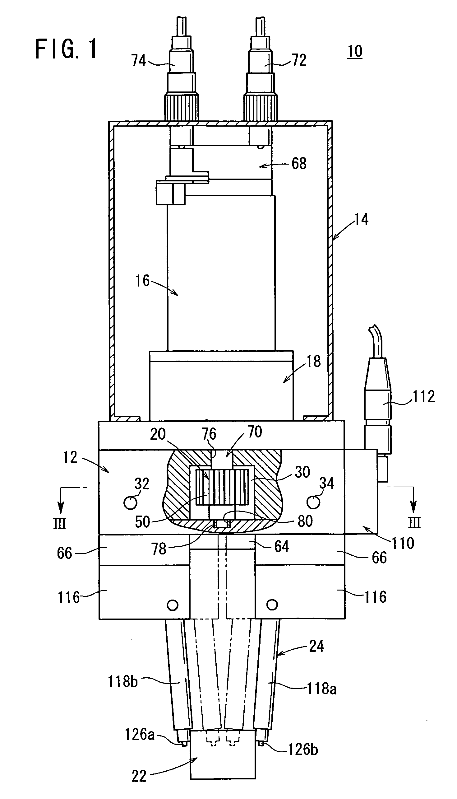
[0024] With reference to FIG. 1, reference numeral 10 indicates a workpiece-gripping chuck according to an embodiment of the present invention.
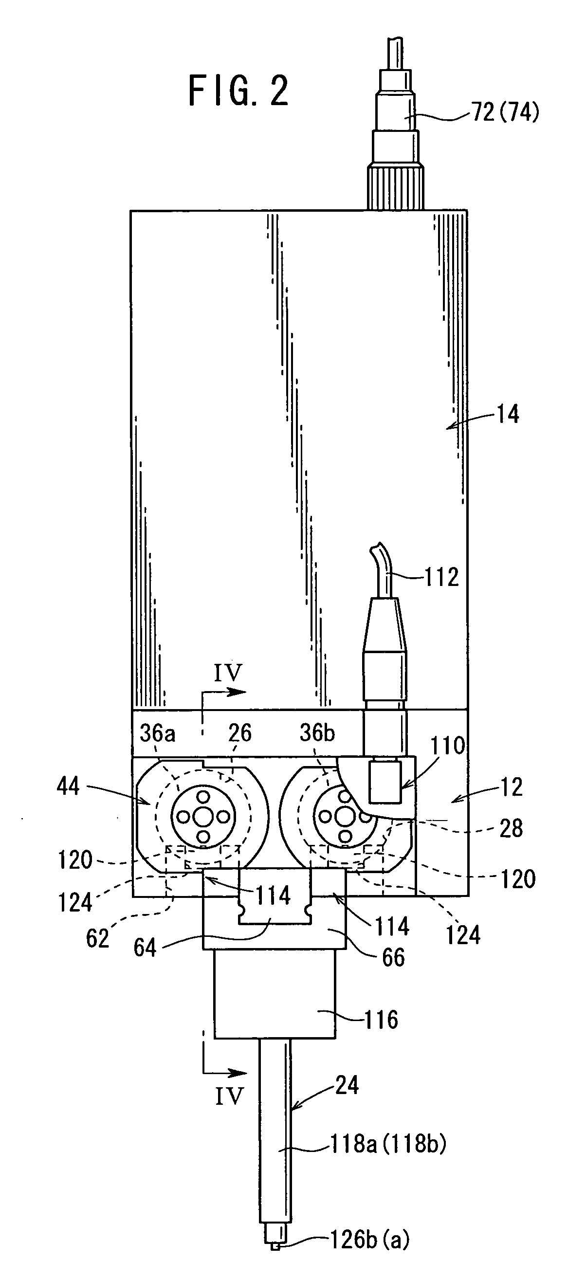
[0025] As shown in FIGS. 1 and 2, the workpiece-gripping chuck 10 (hereinafter simply referred to as “gripping chuck 10”) comprises a body 12 having a substantially rectangular cross section, a casing 14 provided on the body 12, a rotary driving source 16 provided in the casing 14, a gear section 18 which effects a speed change of the driving force supplied from the rotary driving source 16, a converting mechanism 20 that converts the driving force subjected to the speed change by the gear section 18 into a rectilinear motion, and a gripping section 24, which is provided under the body 12 and which grips a workpiece 22 by an opening / closing action thereof.
[0026] As shown in FIG. 3, the body 12 includes a pair of first and second through holes 26, 28 formed therein in the axial direction, a communication hole 30 formed at a substantially cen...
PUM
 Abstract
Description
Claims
Application Information
 - R&D
- Intellectual Property
- Life Sciences
- Materials
- Tech Scout
- Unparalleled Data Quality
- Higher Quality Content
- 60% Fewer Hallucinations
Browse by: Latest US Patents, China's latest patents, Technical Efficacy Thesaurus, Application Domain, Technology Topic, Popular Technical Reports.
© 2025 PatSnap. All rights reserved.Legal|Privacy policy|Modern Slavery Act Transparency Statement|Sitemap|About US| Contact US: help@patsnap.com


