Strain energy shuttle apparatus and method for vibration energy harvesting

Active Publication Date: 2006-08-10
THE BOEING CO
View PDF3 Cites 55 Cited by
  • Summary
  • Abstract
  • Description
  • Claims
  • Application Information

AI Technical Summary

Benefits of technology

[0013] Further areas of applicability of the present invention will become apparent from the detailed description provided hereinafter. It should be understoo

Problems solved by technology

When subjected to vibration, the tip of the beam tends to resist motion, thus placing the piezo material under stress.
This stress results in electrical charge accumulation in the piezo material that results in an increase in voltage potential between two points of the material.
However, for this topology to work efficiently, vibration energy must occur at or above the beam resonance frequency.
Additionally, piezo material is usually a ceramic and is fragile when subjected to tension loading which will limit the robustness of the VEH device and its life. FIG. 2 illustrates the relative tip displacement as a f

Method used


Image

  • Strain energy shuttle apparatus and method for vibration energy harvesting
  • Strain energy shuttle apparatus and method for vibration energy harvesting
  • Strain energy shuttle apparatus and method for vibration energy harvesting

Examples


Embodiment Construction

[0021] The following description of the preferred embodiment(s) is merely exemplary in nature and is in no way intended to limit the invention, its application, or uses.

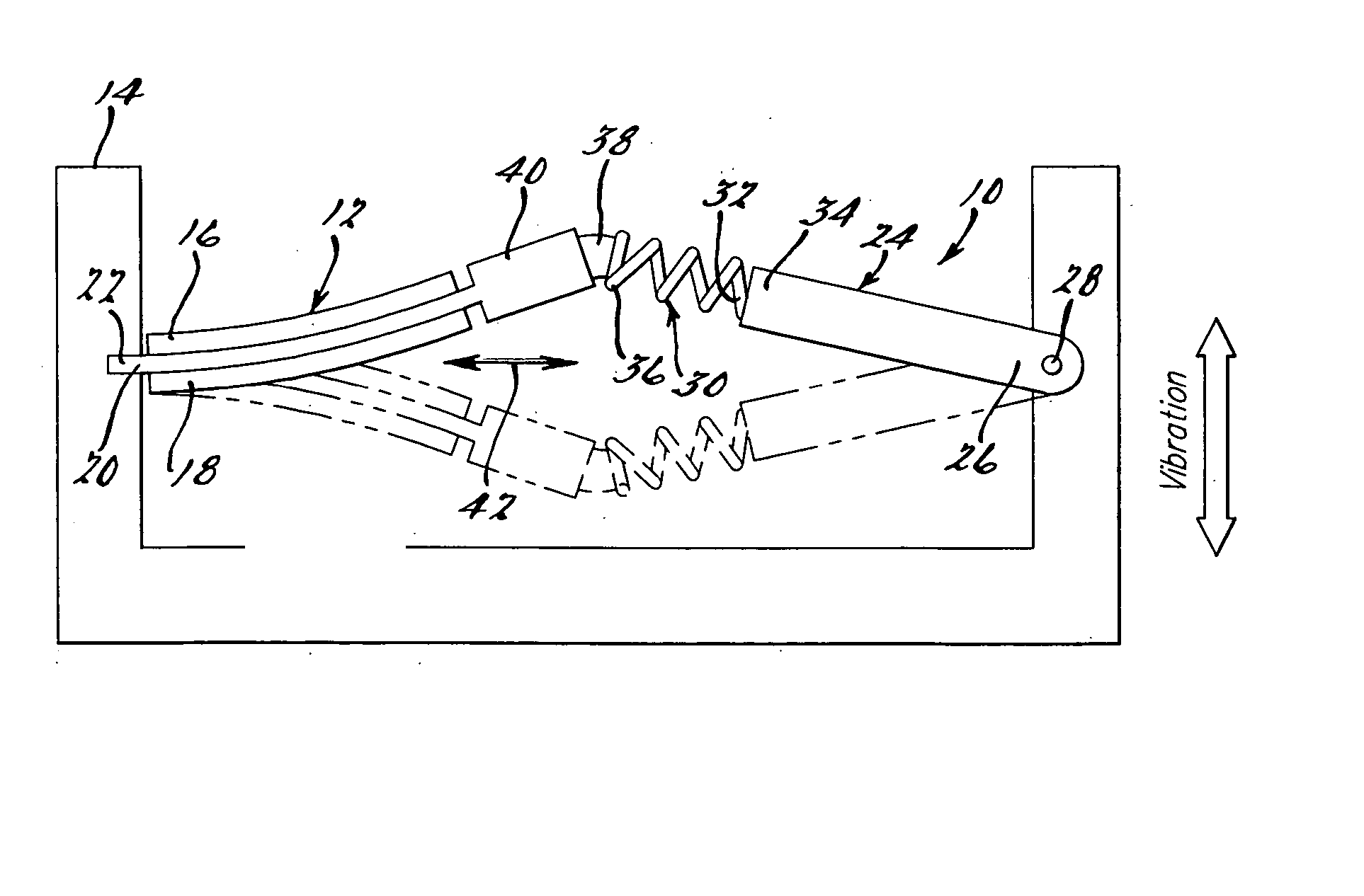
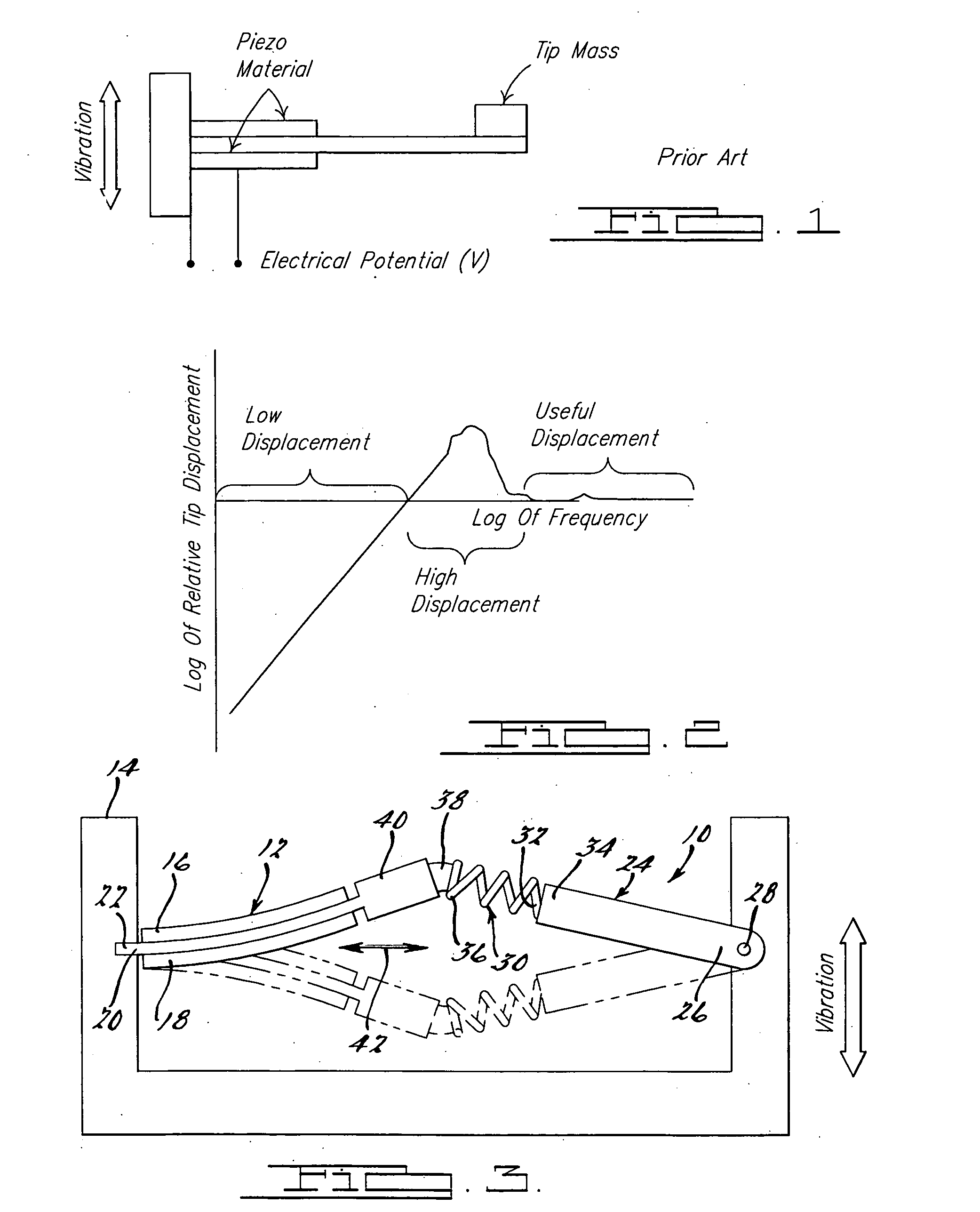
[0022] Referring to FIG. 3, an apparatus 10 in accordance with a preferred embodiment of the present invention is shown. The apparatus is used for enabling low frequency vibration energy harvesting (VEH) through the use of a piezo flexure 12 which is supported fixedly from a vibrating structure 14. The piezo flexure essentially forms a beam-like structure, and in one preferred form comprises a piezo bimorph flexure. The piezo flexure 12 includes piezo layers 16 and 18 formed on opposite sides of a flexible supporting substrate 20. The substrate 20 includes an end 22 which is fixedly coupled to the structure 14. The substrate 20 can be plastic, metal or any other flexible material that allows the piezo layers 16 and 18 to be bonded thereto.

[0023] The apparatus 10 further includes a link or cantilever beam 24 which i...


PUM


Abstract

An apparatus for use in low frequency vibration energy harvesting (VEH) and with actuators requiring a low deflection force. The apparatus includes a piezo flexure that is loaded with a compressive pre-load force to place the piezo flexure under compression. The piezo flexure may be supported at an intermediate point or at one end thereof. The compressive pre-load force produces flexes the piezo flexure into one or the other of two stable positions, these positions being offset on opposite sides of a longitudinal centerline representing the position of the piezo flexure that would be produced without the compressive pre-load force applied thereto. The compressive pre-load effectively provides a negative spring constant which “softens” the piezo flexure and enhances a responsiveness of the piezo flexure to low frequency vibration energy. The piezo flexure also operates over a much wider frequency bandwidth than conventional systems incorporating a tip mass.

Description

CROSS-REFERENCE TO RELATED APPLICATIONS [0001] This application is a continuation of International Patent Application Ser. No. PCT / US / 2004 / 025049 filed Jul. 30, 2004, which in turn claims priority from U.S. Patent Provisional Application No. 60 / 491,122 filed Jul. 30, 2003, the disclosures of which are incorporated herein by reference.FIELD OF THE INVENTION [0002] This invention relates to vibration energy harvesting devices, and more particularly to an apparatus which is ideally suited for harvesting low frequency vibration energy from a vibrating structure. BACKGROUND OF THE INVENTION [0003] Many environments offer a vibration rich environment that is ideal for harvesting vibration energy. Such environments often exist in aircraft and automotive applications where the vibration experienced by an aircraft or automotive vehicle represents energy that could be used to power sensors or other remotely located devices, provided such energy can be harvested by a suitable device. [0004] Vi...

Claims


Application Information

Patent Timeline
IPC IPC(8): H01L41/113
CPCH01L41/1136H02N2/186H10N30/306
Inventor CLINGMAN, DAN J.RUGGERI, ROBERT T.
Owner THE BOEING CO
Why Eureka
Try Eureka