Floating heatsink for removable components

Active Publication Date: 2006-08-10
CIENA
View PDF9 Cites 21 Cited by
  • Summary
  • Abstract
  • Description
  • Claims
  • Application Information

AI Technical Summary

Benefits of technology

[0011] Further, in some embodiments there may be provided a second resilient bias element to augment the bias provided by the resilient bias member

Problems solved by technology

Such electromagnetic radiation can disturb the functioning of other nearby electronic equipment, and vice versa.
This approach does not provide for ready

Method used


Image

  • Floating heatsink for removable components
  • Floating heatsink for removable components
  • Floating heatsink for removable components

Examples


Embodiment Construction

[0022] Certain terminology may be employed in the description to follow for convenience rather than for any limiting purpose. For example, the terms “top”, “bottom”, “forward”, “rearward”, “right”, “left”, “rightmost”, “leftmost”, “upper”, and “lower” designate directions in the drawings to which reference is made. Terminology of similar import other than the words specifically mentioned above is likewise to be considered as being used for purposes of convenience rather than in any limiting sense. In the description and figures to follow, corresponding characters are used to designate corresponding elements throughout the several views, with equivalent elements being referenced with prime or sequential alphanumeric designations where appropriate to assist understanding.

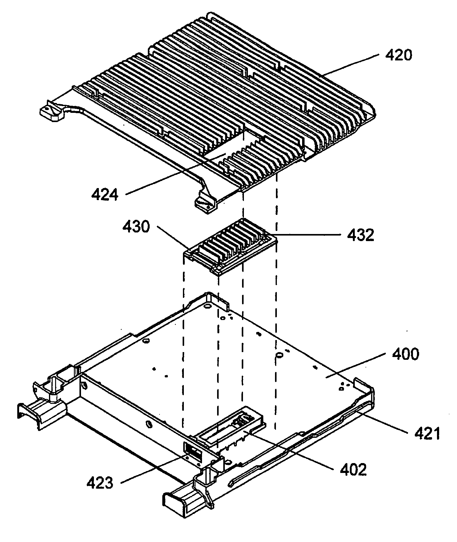
[0023] Modern electronic circuit assemblies are progressively moving towards denser and denser concentrations of heat generating components within given package sizes. Increased density brings a need for enhanced mea...


PUM


Abstract

A floating heatsink is disclosed for components mounted within an electromagnetic enclosure. The floating heatsink includes an aperture within the enclosure wall against which a floating heatsink is disposed on the interior of the enclosure. The floating heatsink is dimensioned to overlap the enclosure around the aperture. A resilient bias member is disposed along the overlap between the floating heatsink and the enclosure. The resilient bias member acts as an electromagnetic gasket while urging the floating heatsink against the component. In certain embodiments the component is replaceable via a second aperture in the enclosure. The floating heatsink is particularly useful for overcoming the need for thermal compounds of heatsinks using the enclosure known in the art.

Description

CROSS-REFERENCE TO RELATED APPLICATIONS [0001] This application is a continuation-in-part of U.S. patent application Ser. No. 10 / 945,075, filed on Sep. 20, 2004, and owned in common herewith.FIELD OF THE INVENTION [0002] The present invention relates to a floating heatsink for removable components and is particularly concerned with heatsinks for components requiring removal for servicing or replacement. BACKGROUND OF THE INVENTION [0003] Heat dissipation is a by-product of most modern electronic equipment, and when heat dissipation from a component or assembly is sufficiently large, heatsinks are used to keep the component or assembly at a sufficiently low temperature. [0004] An additional requirement of high-speed electronics is the containment and / or shielding of electromagnetic radiation developed by the circuitry during operation. Such electromagnetic radiation can disturb the functioning of other nearby electronic equipment, and vice versa. In order to contain electromagnetic r...

Claims


Application Information

Patent Timeline
IPC IPC(8): G06F1/20
CPCG06F1/20
Inventor SATURLEY, PETERATKINSON, JOHN CLAYTON
Owner CIENA
Why Eureka
Try Eureka