
Method and apparatus for storing and defining light shows

a technology for defining and storing light shows, applied in lighting and heating apparatus, electroluminescent light sources, lighting support devices, etc., can solve the problems of large amount of data, affecting the perceived speed and seamlessness of the show, and the cost of memory chips is a significant portion of manufacturing costs, so as to reduce size and cost

Inactive Publication Date: 2006-08-10
SC JOHNSON & SON INC
View PDF27 Cites 59 Cited by
  • Summary
  • Abstract
  • Description
  • Claims
  • Application Information

AI Technical Summary

Benefits of technology

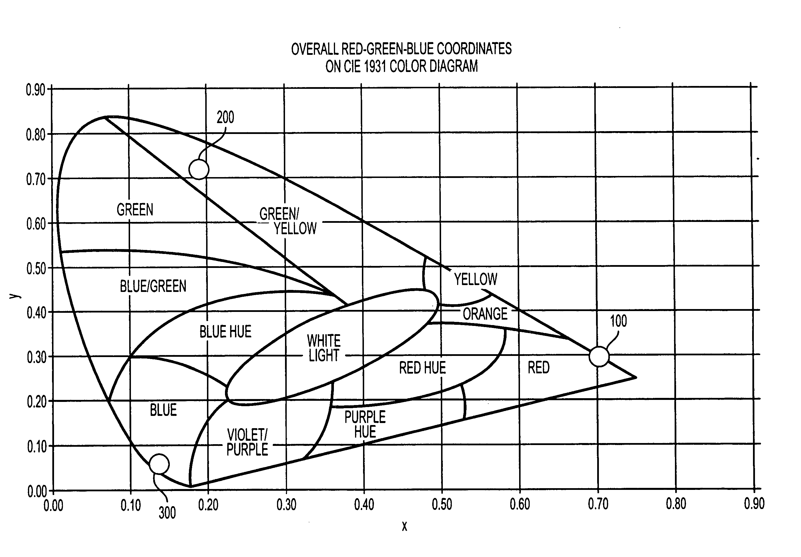
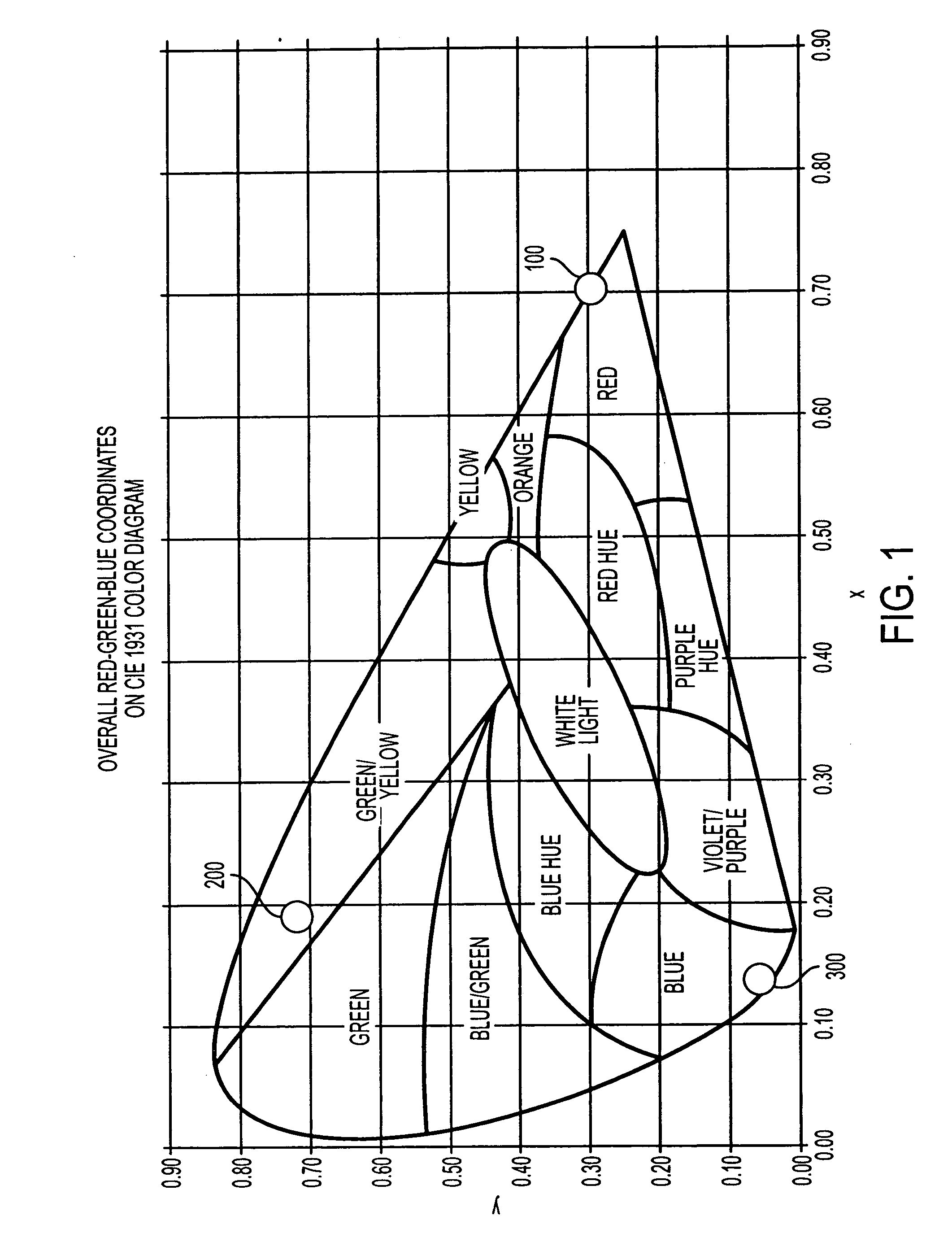
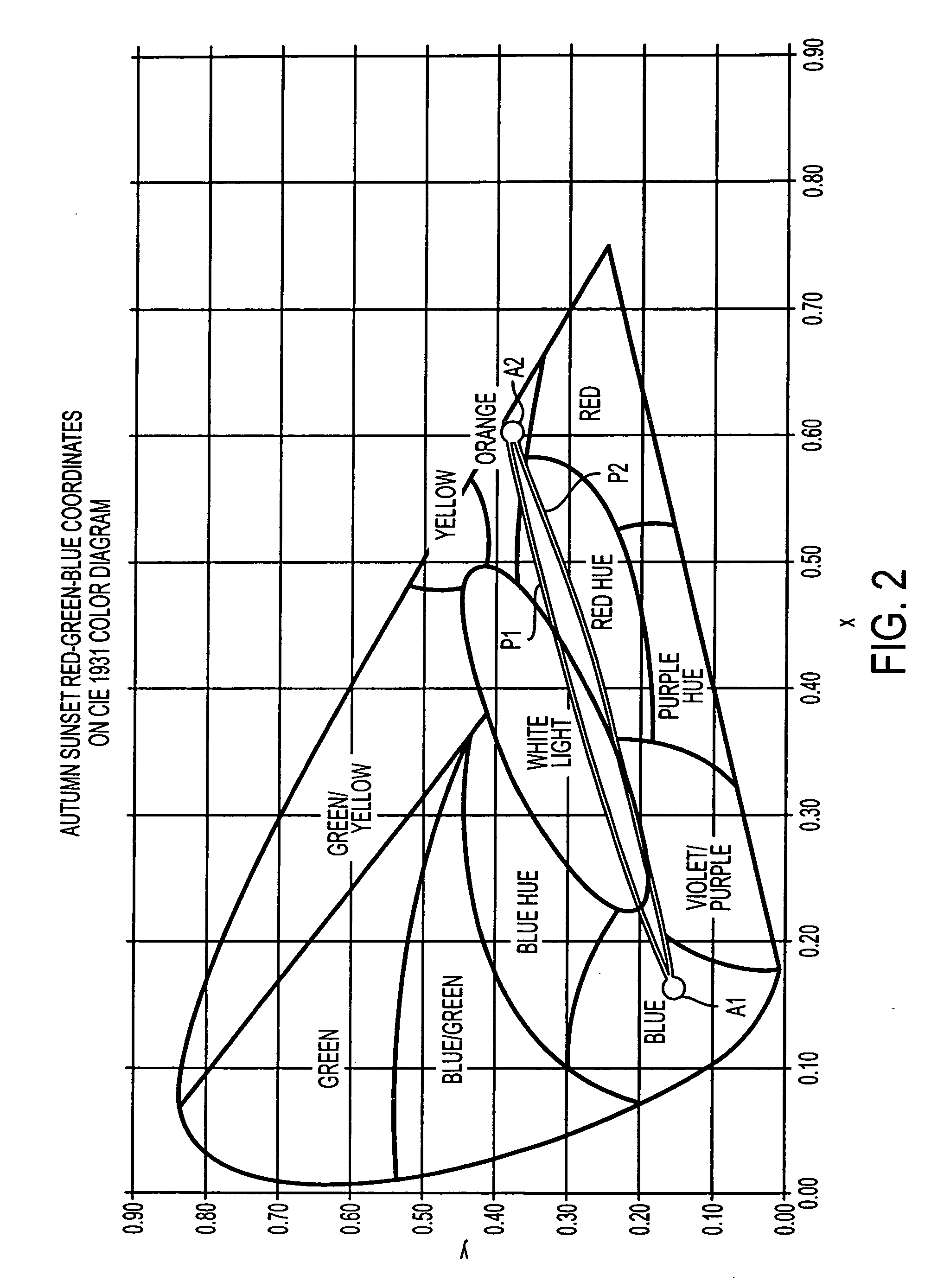
[0021] With this invention, the intervening color points of the light show between the starting color point and ending color point need not be stored in a look-up table. Instead, a microcontroller can be programmed to calculate the intervening points using the data identifying the starting and ending (or target) points and the timing information for traveling between those points to produce the light show, as will be discussed in more detail later. This allows a memory storing one or more light shows to be reduced in size and cost. It also provides a light show designer with a simplified process for defining and altering a light show in order to achieve a desired effect.

Problems solved by technology

Of course, the distance between the color points used will affect the perceived speed and the seamlessness of the show.
This can lead to a relatively large amount of data, particularly if multiple light shows are to be stored in the memory and the device is a simple device for which the cost of memory chips is a significant portion of the manufacturing cost.

Method used


Image

  • Method and apparatus for storing and defining light shows
  • Method and apparatus for storing and defining light shows
  • Method and apparatus for storing and defining light shows

Examples


Embodiment Construction

Defining and Storing a Light Show

[0037] As discussed above, one embodiment of our invention is directed to defining and storing a light show in such a way as to reduce the memory needed to store the show and provide a designer with ease of control over programming and altering the light show.

[0038] Our improved system involves defining the target (or ending) color point of the light show, and in some cases, the starting color point. A color point refers to the settings of the LEDs at a given moment of the light show, which provides a specific perceived color. (As the settings of the LEDs change over time in accordance with the instructions for the light show, the successive color points of the show can ultimately be perceived as a “wash” or “waves” of colors.) Because we are discussing “perceived” colors, the starting color point does not directly correspond to the wavelengths of light emitted by the LEDs used in the color show, inasmuch as those wavelengths are substantially con...


PUM


Abstract

Lighting object for providing a light show to an observer. The lighting object includes at least two LEDs, each of which emits light of a different wavelength, and a microcontroller for independently controlling the intensity levels of the at least two LEDs to vary colors perceived by the observer during the light show. The light show includes at least one segment for which a memory stores, for each of the at least two LEDs, a target intensity level and timing information. The microcontroller calculates a plurality of intermediate intensity levels for the at least two LEDs for the duration of the segment based on a starting intensity level, the target intensity level, and the timing information for each of the at least two LEDs. The microcontroller also controls the at least two LEDs to operate at each of the calculated intermediate intensity levels during the segment.

Description

BACKGROUND OF THE INVENTION [0001] 1. Field of the Invention [0002] Our invention is directed to designing and storing light shows to be used in light objects. Light objects include any object that is intended to provide light for illumination or decoration. Light objects, therefore, include projectors, light bulbs for conventional light sockets, internally lit sculptures, night lights, etc. Our invention is also directed to novel light shows for use in light objects. More specifically, our invention is directed to using various formulae and / or CIE (Commission Internationale de l'Eclairage) coordinates to define the colors to be used in a light show and the manner in which the colors change over the course of a light show. [0003] 2. Description of the Related Art [0004] Home lighting effects have proven important and desirable to consumers seeking settings anywhere from soothing to dramatic. In particular, dimmers and specialized light shades have provided consumers with the ability...

Claims


Application Information

Patent Timeline
Patent Type & Authority Applications(United States)
IPC IPC(8): F21V9/00H05B44/00F21V9/40G09G3/32
CPCH05B33/0803H05B33/0818H05B33/0863H05B37/029H05B45/20H05B47/155H05B45/325
Inventor WALTER, SCOTT D.DECHANT, EDWARD J.DEMAREST, SCOTT W.KARA J.
Owner SC JOHNSON & SON INC
Learn More