
Performance monitoring for optical links

a technology of optical links and performance monitoring, applied in transmission monitoring, transmission monitoring/testing/fault measurement systems, digital transmission, etc., can solve the problems of many costly solutions for performance monitoring of optical links, failure, and only working for a limited dispersion rang

Inactive Publication Date: 2006-08-10
WSOU INVESTMENTS LLC
View PDF4 Cites 4 Cited by
  • Summary
  • Abstract
  • Description
  • Claims
  • Application Information

AI Technical Summary

Benefits of technology

[0012] In a preferred variant, the comparison in step (c) is carried through by a maximum likelihood estimation, in particular by calculating a minimum square error. In this way, an easy comparison of the reference parameter sets with the first parameter set is provided.
[0015] In a highly preferred variant, the given sequence of bit patterns is derived from a sequence of transmitted bits. In this way, an on-line determination of optical link parameters for a transmitted signal is possible.

Problems solved by technology

There have been proposed many costly solutions for performance monitoring of optical links, including optical measurement techniques as well as techniques which use additional modulation tones (not in the standard).
Due to the limited parameter set (taps) it works only for a limited dispersion range or fails if mixed distortions are present (e.g. PMD and CD).

Method used


Image

  • Performance monitoring for optical links
  • Performance monitoring for optical links

Examples


Embodiment Construction

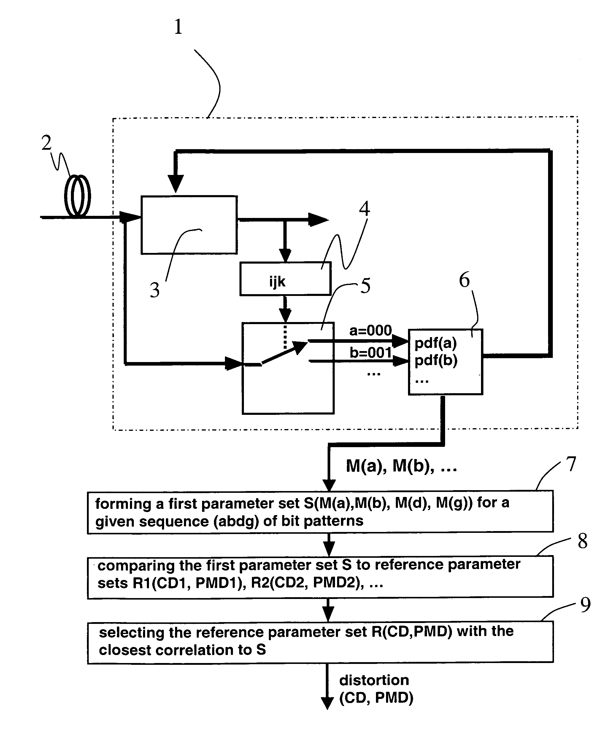
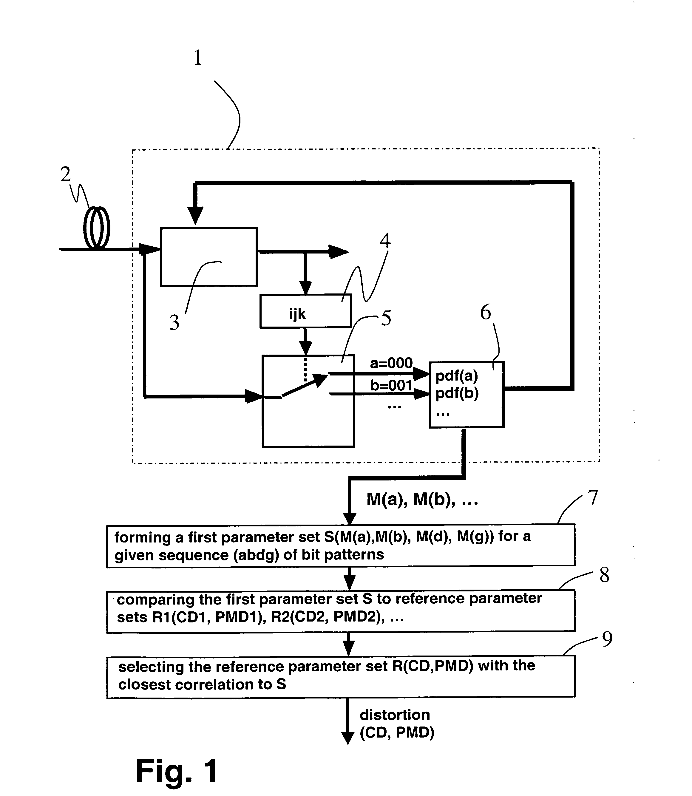
[0021] The technique explained below is based on the existence of a Viterbi equalizer 1 as shown in FIG. 1. The Viterbi equalizer 1 (maximum-likelihood sequence detector) may be implemented in the receiver line card of an optical receiver (not shown). For its adaptation, the Viterbi equalizer 1 extracts detailed information on the distortion of an optical signal transmitted through an optical link 2, the optical signal being converted to an analog electrical signal by a photodiode (not shown) at the entrance of the Viterbi equalizer 1. The analog electrical signal is converted to a digital bit sequence in a Viterbi core 3.

[0022] Depending on the subsequent bits appearing at the output of the Viterbi core 3, a shift register 4 distributes the input to the Viterbi core 3 to one of the output channels of a multiplexer 5. The outputs are fed into a histogram generator 6. Commonly the signal at the input of the multiplexer 5 is analog-to-digital converted (not shown in the FIGURE) and t...


PUM


Abstract

A method for estimating at least one optical link parameter using a Viterbi equalizer (1) generating averaged values (M) of signal amplitudes of a distorted optical signal transmitted through an optical link (2) for a set of decided bit patterns (a, b, c, d, . . . ), the method comprising the following steps: forming a first parameter set (S) characteristic of a distorted signal sequence using the averaged values (M(a), M(b), M(d), M(g)) for a given sequence (abdg) of bit patterns (a, b, c, d, . . . ), comparing the first parameter set (S) to a plurality of reference parameter sets (R1, R2, . . . ) characteristic for reference signal sequences of the same sequence (abdg) of bit patterns (a, b, c, d, . . . ), each of the reference parameter sets (R1, R2, . . . ) having a known value of the at least one optical link parameter, and selecting the reference parameter set (R) with the closest correlation to the first parameter set (S), the known value of the at least one optical link parameter of the selected reference parameter set (R) being used as an estimate for the at least one optical link parameter. A computer program product comprising a software or a hardware implementing the method.

Description

[0001] The invention is based on a priority application EP 05290259.0 which is hereby incorporated by reference. FIELD OF THE INVENTION [0002] The invention relates to a method for estimating at least one optical link parameter. BACKGROUND OF THE INVENTION [0003] For performance monitoring of 10 Gb / s (future 40 Gb / s) transmission systems, it is mandatory to obtain a reliable estimate of the status of optical transmission links for preemptive fault detection for network management or network control. This status can be described by optical link parameters being characteristic of the distortion of an optical signal transmitted through the optical fiber link, such as chromatic dispersion (CD), polarization mode dispersion (PMD), self-phase modulation (SPM), etc. [0004] There have been proposed many costly solutions for performance monitoring of optical links, including optical measurement techniques as well as techniques which use additional modulation tones (not in the standard). At t...

Claims


Application Information

Patent Timeline
IPC IPC(8): H04B10/08H04B10/00
CPCH04B10/00H04L25/03178
Inventor BULOW, HENNING
Owner WSOU INVESTMENTS LLC
Learn More