Method for producing a mask layout avoiding imaging errors for a mask

a mask and mask technology, applied in the field of mask layouts, can solve the problems of relatively time-consuming division of main structures into segments, and achieve the effect of avoiding imaging errors

Inactive Publication Date: 2006-08-10
INFINEON TECH AG
View PDF11 Cites 183 Cited by
  • Summary
  • Abstract
  • Description
  • Claims
  • Application Information

AI Technical Summary

Benefits of technology

[0017] In one aspect, the invention specifies a method for producing a final mask lay

Problems solved by technology

Specifically, it is precisely the division of the main st

Method used


Image

  • Method for producing a mask layout avoiding imaging errors for a mask
  • Method for producing a mask layout avoiding imaging errors for a mask
  • Method for producing a mask layout avoiding imaging errors for a mask

Examples


Embodiment Construction

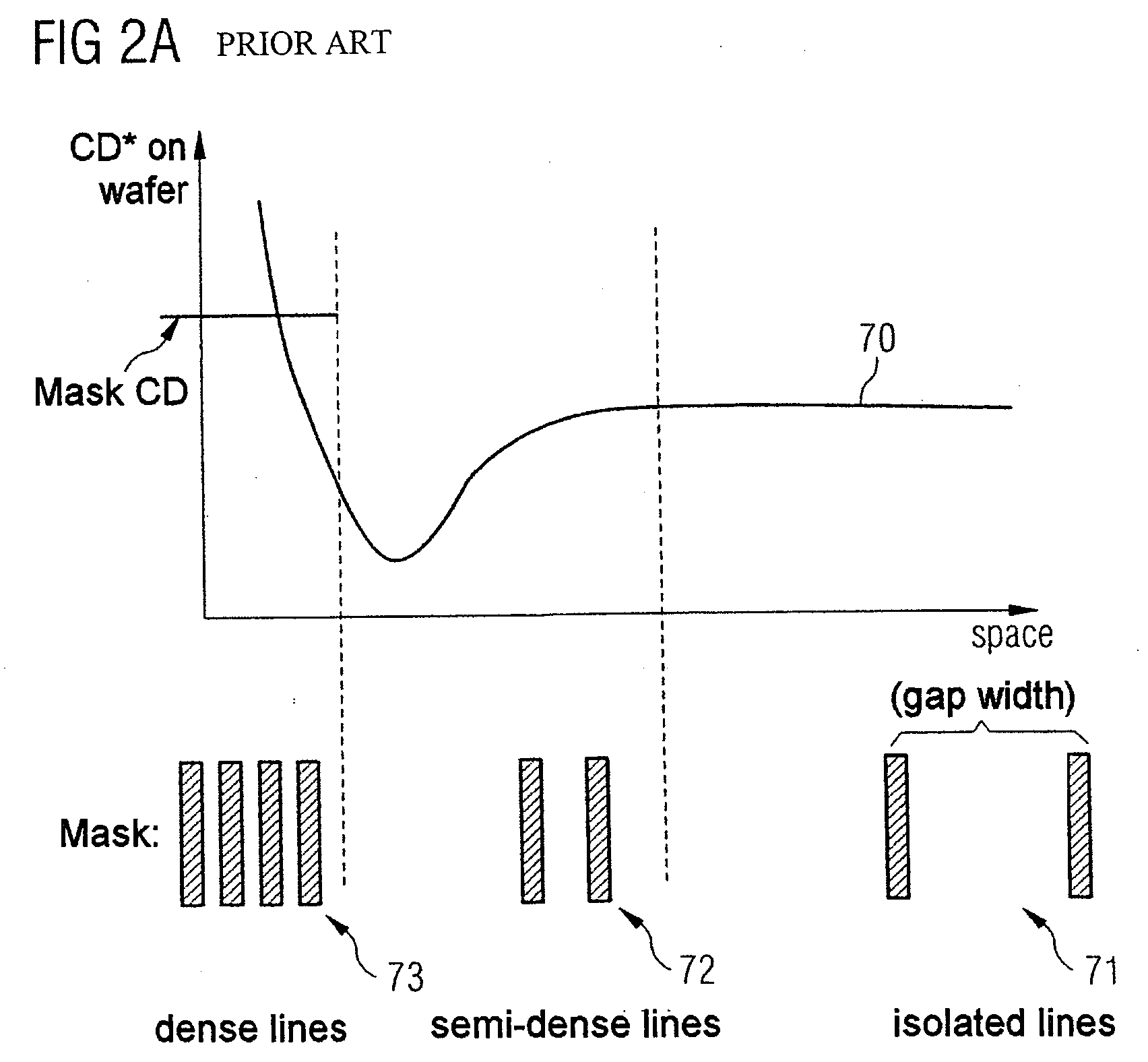
[0071]FIG. 2A illustrates an OPC curve 70 specifying how the CD values vary in a manner dependent on the distance between the main structures, for example, in the case of lines. In the case of isolated lines 71, the CD value is largely independent of the distance between the structures. In the case of average, semi-dense main structures 72, the CD value falls in the direction of smaller structure distances before it rises significantly again in the case of very dense structures 73.

[0072] In this case, the OPC curve 70 describes the CD value profile on the wafer given a constant mask CD value, which is likewise depicted in FIG. 2A for comparison.

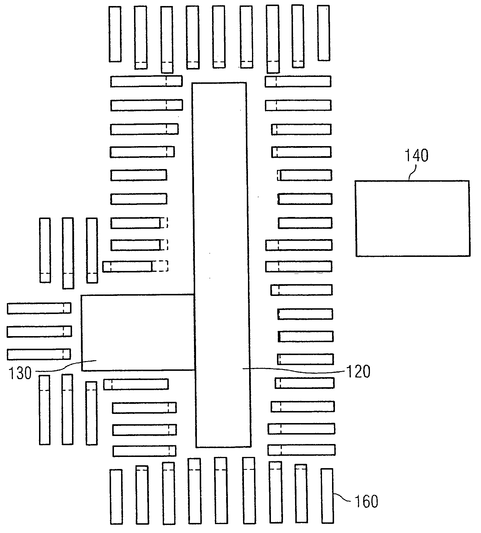
[0073]FIG. 3 reveals a provisional auxiliary mask layout 110 comprising main structures 120, 130 and 140. The three main structures 120, 130 and 140 are in each case formed by rectangles. Two main structures 120 and 130 directly adjoin one another in this case.

[0074]FIG. 4 shows, on the basis of the main structures 120 and 130, how the pro...


PUM


Abstract

A method for producing a final mask layout (20′) avoids imaging errors. A provisional auxiliary mask layout (110) is produced, in particular in accordance with a predefined electrical circuit diagram, and is converted into the final mask layout (20′) with the aid of an OPC method. A main structure (120, 130) of the provisional auxiliary mask layout (110) is assigned optically non-resolvable auxiliary structures (160, 320). Exclusively the optically non-resolvable auxiliary structures (160, 320) are altered in the context of the OPC method, and the main structure (120, 130) itself remains unaltered.

Description

[0001] This application claims priority to German Patent Application 10 2005 002 533.1, which was filed Jan. 14, 2005, and is incorporated herein by reference. TECHNICAL FIELD [0002] The invention relates to a method for producing a mask layout that minimizes imaging errors for a mask. BACKGROUND [0003] It is known that, in lithography methods, imaging errors can occur if the structures to be imaged become very small and have a critical size or a critical distance with respect to one another. The critical size is generally referred to as the “CD” value (CD: critical dimension). [0004] What is more, imaging errors may occur if structures are arranged so closely next to one another that they mutually influence one another during the imaging. These imaging errors, based on “proximity effects,” can be reduced by modifying the mask layout beforehand with regard to the “proximity phenomena” that occur. Methods for modifying the mask layout with regard to avoiding proximity effects are ref...

Claims


Application Information

Patent Timeline
IPC IPC(8): G03C5/00G06F17/50G03F1/00G03F1/36
CPCG03F1/144G03F1/36G03F7/70441
Inventor BODENDORF, CHRISTOFKURTH, KARINMEYNE, CHRISTIANNASH, EVA
Owner INFINEON TECH AG
Why Eureka
Try Eureka