Connector

a technology of connectors and functions, applied in the direction of coupling parts engagement/disengagement, coupling device connections, drilling pipes, etc., can solve the problems of low sealing performance of seals, difficulty in fitting connectors together with respective front surfaces, and both connectors being oriented together in a downward posture, so as to improve sealing performance, improve sealing performance, and improve sealing performance.

Active Publication Date: 2006-08-10
SUMITOMO WIRING SYST LTD
View PDF5 Cites 37 Cited by
  • Summary
  • Abstract
  • Description
  • Claims
  • Application Information

AI Technical Summary

Benefits of technology

[0008] The invention relates to a connector with a housing made of synthetic resin and terminal fittings accommodated in the housing. Electric wires are fixed respectively to the terminal fittings and extend outside from a rear surface of the housing. A tubular rubber boot is mounted on the housing to cover an outer peripheral surface and a rear surface of the housing. Thus, the electric wires penetrate through the rubber boot. The connector is fit in a mating connector so that a front surface of the housing confronts a front surface of a housing of the mating connector. A seal is formed on the rubber boot and elastically contacts the peripheral surface of the housing. The seal seals the gap between the inner peripheral surface of the rubber boot and the peripheral surface of the housing so that water cannot penetrate through the gap into the rear surface of the housing. Additionally, the compressive elasticity of the seal is not affected by the posture of the connector when the connector is fit in the mating connector. Therefore, the performance of the seal does not deteriorate in dependence on the posture of the connector when the connector is fit in the mating connector.
[0009] A cover preferably is mounted on the housing and covers the rubber boot so that the seal is sandwiched between the cover and the housing over an entire periphery of the seal. Additionally, the cover preferably is more rigid than the rubber boot. Therefore the compressive elasticity amount of the seal for the periphery of the first housing is uniform over the entire periphery of the seal. Thus, the seal displays a high degree of sealing performance.
[0010] A main lip preferably is formed on an inner peripheral surface of the seal and elastically contacts the peripheral surface of the housing. An auxiliary lip preferably is formed on a peripheral surface of the seal at a position corresponding to the main lip and elastically contacts an inner peripheral surface of the cover. Accordingly, the elastic contact of the auxiliary lip with the cover generates an elastic restoring force that is applied as an elastic contact pressure of the main lip for the first housing. Thus, the sealing performance of the seal is improved.
[0011] The housing and the cover preferably are approximately quadrangular and positioning projections preferably project from peripheral surfaces of at least two of the four sides of the housing. The positioning projections penetrate through the rubber boot and fit in positioning holes of the cover. Thus, the cover is mounted at a predetermined position on the housing, and there are no fluctuations of the dimension of the gap between the peripheral surface of the housing and the inner peripheral surface of the cover. Accordingly, the compressive elasticity of the seal will not fluctuate and the seal displays a high sealing performance.

Problems solved by technology

However, it is difficult to fit the connectors together with the respective front surfaces confronting each other at a high accuracy in view of dimensional and mounting tolerances.
Thus, there is a fear that both connectors will fit together in an inclined posture.
In this case, the compressive elasticity of the seal becomes peripherally nonuniform and there is a fear that the seal will have a low degree of sealing performance.

Method used


Image

  • Connector
  • Connector
  • Connector

Examples


Embodiment Construction

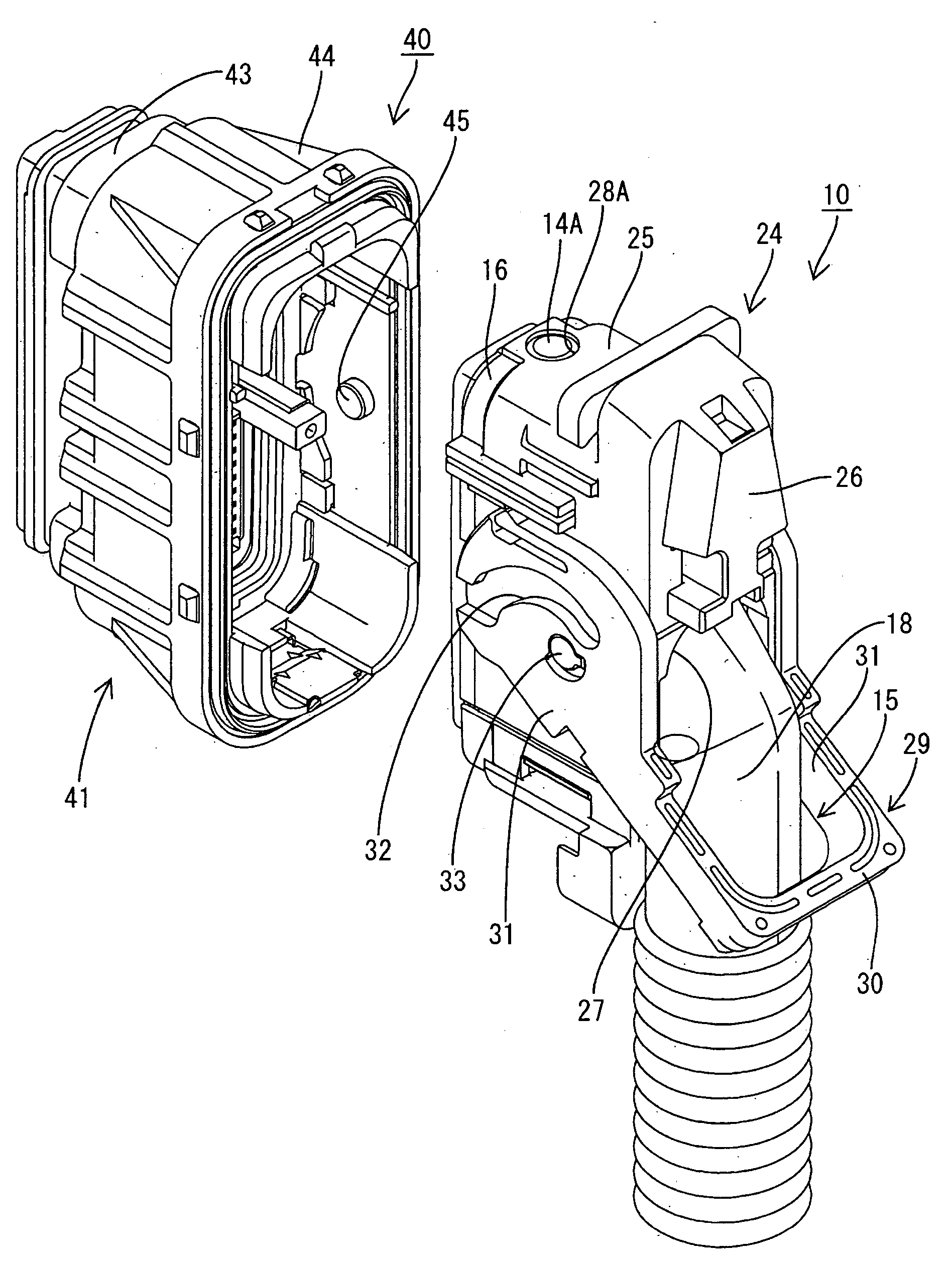
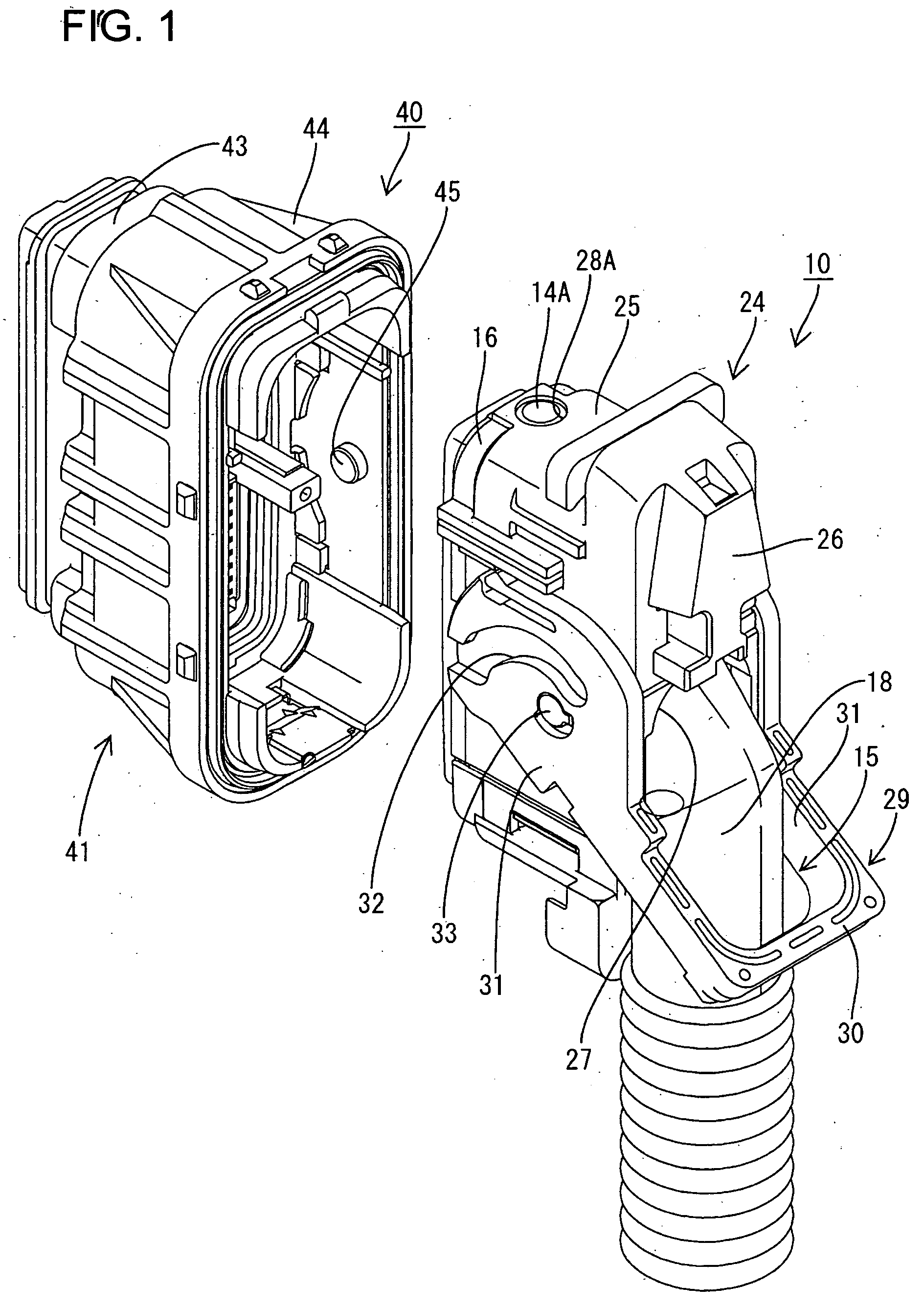
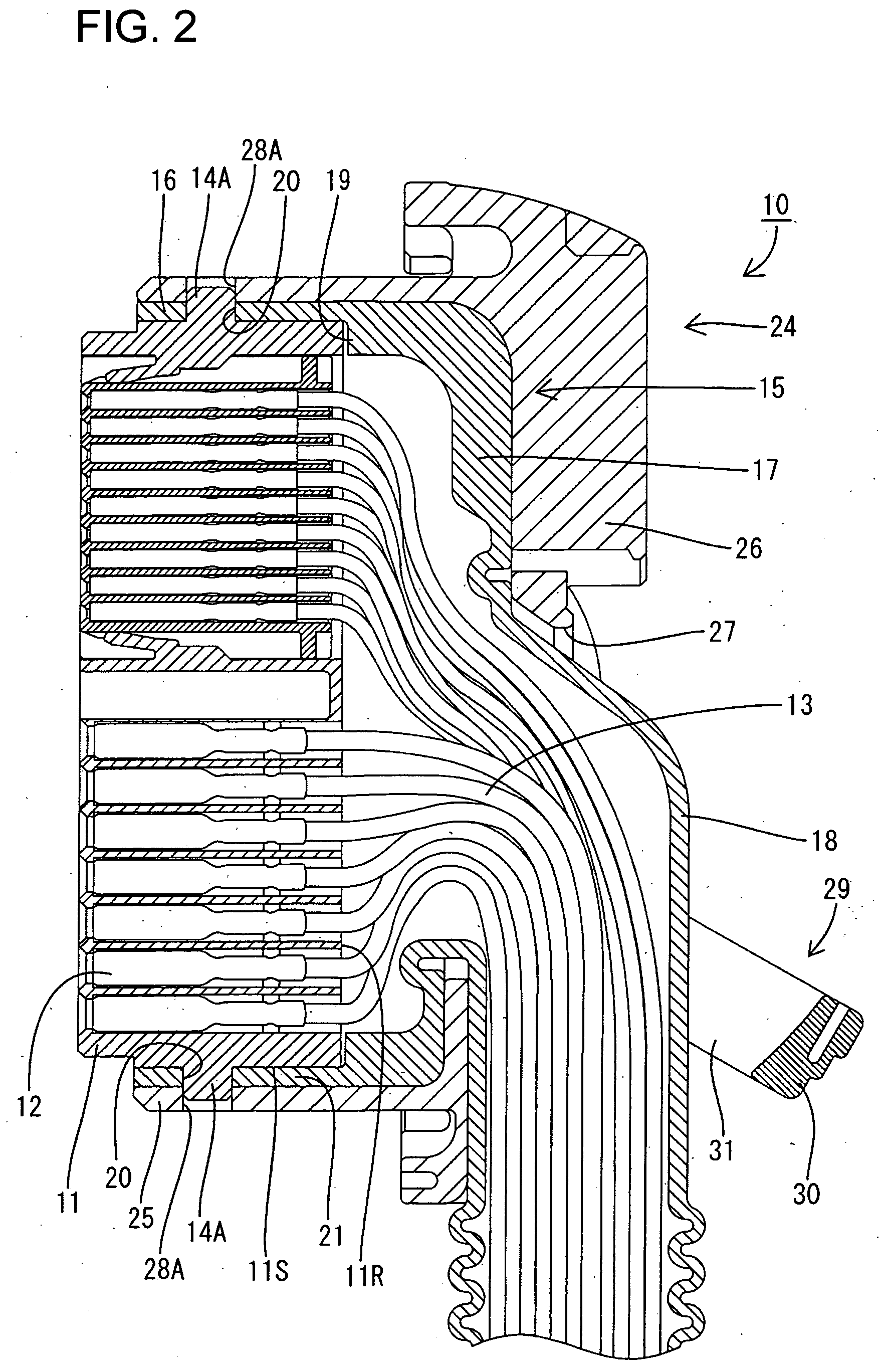
[0021] A connector assembly according to the invention includes first and second connectors identified generally by the numerals 10 and 40 in FIGS. 1 to 9. The first connector 10 has a first housing 11. The first housing 11 is made of synthetic resin and has the shape of a long quadrangular block. First terminal fittings 12 are inserted into the first housing 11 from a rear side thereof. An electric wire 13 is fixed to a rear end of each of the first terminal fittings 12. The electric wire 13 extends to the outside from a rear surface 11R of the first housing 11. Upper and lower positioning projections 14A are formed on upper and lower surfaces of the periphery of the first housing 11 and have column-shaped axes that project vertically in a direction normal to a direction in which the first connector 10 is fit in the second connector 40. Upper and lower positioning projections 14B are formed on left and right surfaces of the periphery of the first housing 11 and have column-shaped a...


PUM


Abstract

A connector (10) has a housing (11) with an outer peripheral surface (11S). A rubber boot (15) has a tubular sealing portion (21) with an inner peripheral surface that mounts over and seals to the outer peripheral surface (11S) of the housing (11). Thus, a compressive elasticity amount of the sealing portion (21) is not affected by a posture of the first connector (10) when the first connector (10) is fit in a second connector (40). Therefore, the sealing performance of the sealing portion (21) does not deteriorate in dependence on the posture of the first connector (10) when the first connector (10) is fit in the second connector (40).

Description

BACKGROUND OF THE INVENTION [0001] 1. Field of the Invention [0002] The invention relates to a connector with a waterproof function. [0003] 2. Description of the Related Art [0004] U.S. Pat. No. 6,685,496 discloses a connector with a waterproof function. More particularly, the known connector with a waterproof function has a housing and terminal fittings are accommodated in the housing. Electric wires are fixed to the respective terminal fittings and extend from a rear end of the housing. The connector further includes a tubular rubber boot that is mounted on the housing. The rubber boot covers both an outer peripheral surface of the housing and the rear end of the housing, and the electric wires penetrate through the rubber boot. A cover is mounted on the housing and covers the rubber boot. [0005] A ring-shaped seal is formed along the edge of an opening of the rubber boot. The seal has a first sealing surface that contacts an end surface of the opening of the cover and a second se...

Claims


Application Information

Patent Timeline
Patent Type & Authority Applications(United States)
IPC IPC(8): E21B17/00
CPCH01R13/516H01R13/5219H01R13/62938
Inventor ISHIKAWA, YOSHIYUKI
Owner SUMITOMO WIRING SYST LTD
Why Eureka
Try Eureka