Apparatus for cleaning pipes having pumping and vacuuming capability

a technology of vacuuming and pipes, applied in the direction of cleaning hollow articles, cleaning equipment, sewer cleaning, etc., can solve the problems of inefficiency or inability to work, inconvenient vacuuming, and inability to vacuum, so as to achieve efficient washing of sewer and other pipe lines, the effect of less efficiency

Inactive Publication Date: 2006-08-17
U S SUBMERGENT TECH LLC
View PDF42 Cites 18 Cited by
  • Summary
  • Abstract
  • Description
  • Claims
  • Application Information

AI Technical Summary

Benefits of technology

[0009] In contrast to the prior waste cleaning apparatus and methods, the apparatus of the present invention is designed to eliminate the need to examine field conditions prior to dispatching a cleaning apparatus to the jobsite. The apparatus of the present invention has improved the overall cost and efficiency of cleaning waste water systems by using a new, novel and non-obvious combination of apparatus and techniques known in the art.

Problems solved by technology

If, for example, there is a large volume of liquid relative to solids in the slurry, vacuuming becomes very inefficient and possibly infeasible.
If very little liquid is present in the waste water system, a pump will be inefficient or may not work at all, and a vacuum is required.

Method used


Image

  • Apparatus for cleaning pipes having pumping and vacuuming capability
  • Apparatus for cleaning pipes having pumping and vacuuming capability
  • Apparatus for cleaning pipes having pumping and vacuuming capability

Examples


Embodiment Construction

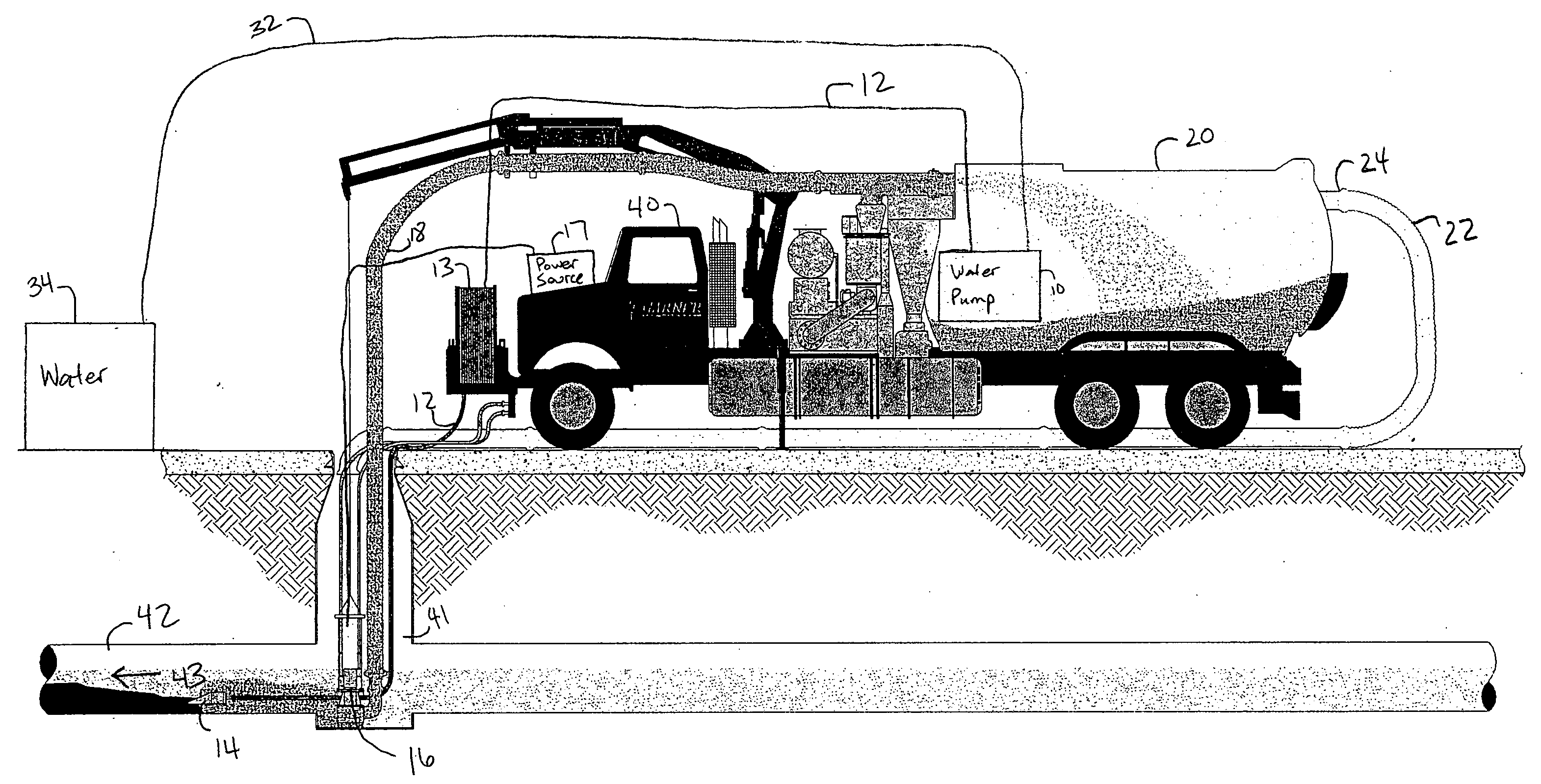
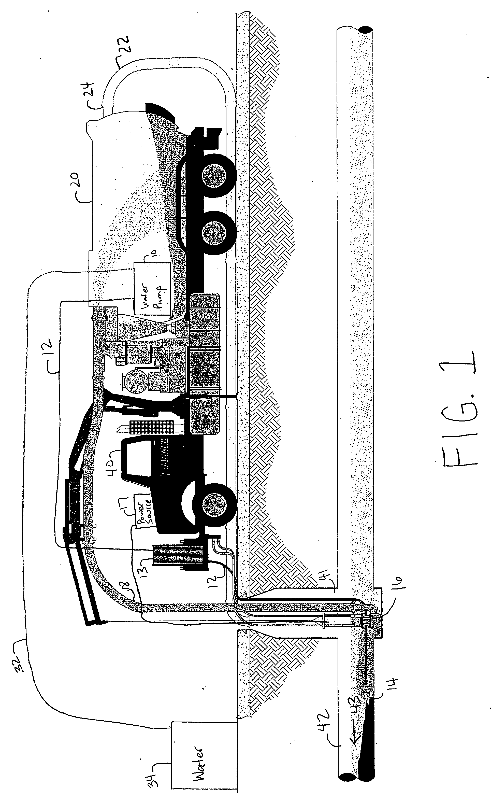
[0033] Referring now to FIGS. 1 and 2, the system of the present invention comprises a high pressure water pump assembly 10 for generating high pressure water, a high pressure water hose 12, a hose reel 13, a bullet-shaped cleaning head 14 for receiving high pressure water and cleaning a sewer, a submersible pump 16 for pumping a slurry of solids and liquids out of the sewer when the slurry contains a large amount of liquid, a power source 17 for the submersible pump 16, a slurry hose 18, a waste container 20 for receiving the pumped slurry, a decant water hose 22, a decant water outlet 24 for releasing the water from the container, main supply water line 32, and main supply water source 34. The invention may be mounted to a truck 40 as seen in FIGS. 1 and 2, or to an immobile unit that must be towed to and from a jobsite. For consistency, the unit will be described as a truck throughout this document.

[0034] The high pressure water pump assembly 10 and pump power source 17 are moun...


PUM


Abstract

An apparatus for cleaning waste collection systems of solid materials. The apparatus is capable of cleaning waste systems in two known ways. First, a pumping method uses normal and injected water flow to suspend the solids in a slurry. A submersible pump moves the slurry from a collection point up to a pressurized container where the water content of the slurry is decanted and reused as injection water while the particulate material settles to the bottom of the pressurized container. Second, a vacuum system may be used to move the slurry from the waste system to the waste container. The vacuum system creates a negative pressure differential, causing material to be pulled through a vacuum tube and into the waste container. When the container becomes substantially full of solid particles, it may be emptied at a dumpsite.

Description

TECHNICAL FIELD [0001] The present invention relates generally to cleaning waste collection systems such as but not limited to sewers, sumps, wet wells, collection tanks, digesters, clarifiers, classifiers, etc. and in particular to cleaning and removal of solid and liquid materials therefrom. BACKGROUND OF THE INVENTION [0002] Waste collection systems such as sewers, sumps, wet wells, digesters, clarifiers, classifiers, collection tanks, etc. must be cleaned periodically in order to maintain proper fluid flow and capacity. Cleaning removes sand and other deleterious materials that have infiltrated into, for example, a sewer as well as solid materials that have settled out from the normally slow moving waste slurry that varies in volume and flow rate depending on the collective amount of effluents emptied into the waste collection system over time. In order to properly clean large capacity waste collection systems such as collection tanks or the vast lengths of sewer lines in a typi...

Claims


Application Information

Patent Timeline
Patent Type & Authority Applications(United States)
IPC IPC(8): E01H1/08
CPCB08B9/043B08B9/0495E03F7/10E03F9/00
Inventor POLSTON, HENRY B.
Owner U S SUBMERGENT TECH LLC
Why Eureka
Try Eureka