Lintel

a technology of lintel and lintel body, which is applied in the field of lintel, can solve the problems of inconvenient transportation of concrete lintels over large distances, limited length of lintel, and inability to meet the needs of construction, so as to increase the bonding strength, and increase the load capacity of lintel

Inactive Publication Date: 2006-08-17
CAST CRETE CORP
View PDF48 Cites 5 Cited by
  • Summary
  • Abstract
  • Description
  • Claims
  • Application Information

AI Technical Summary

Benefits of technology

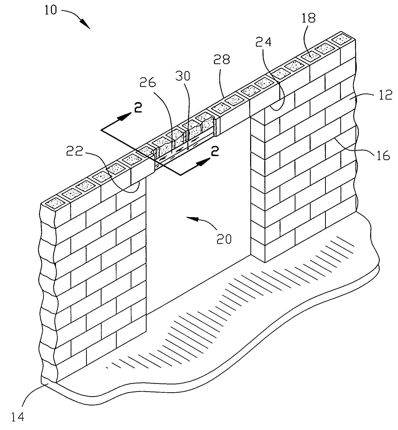
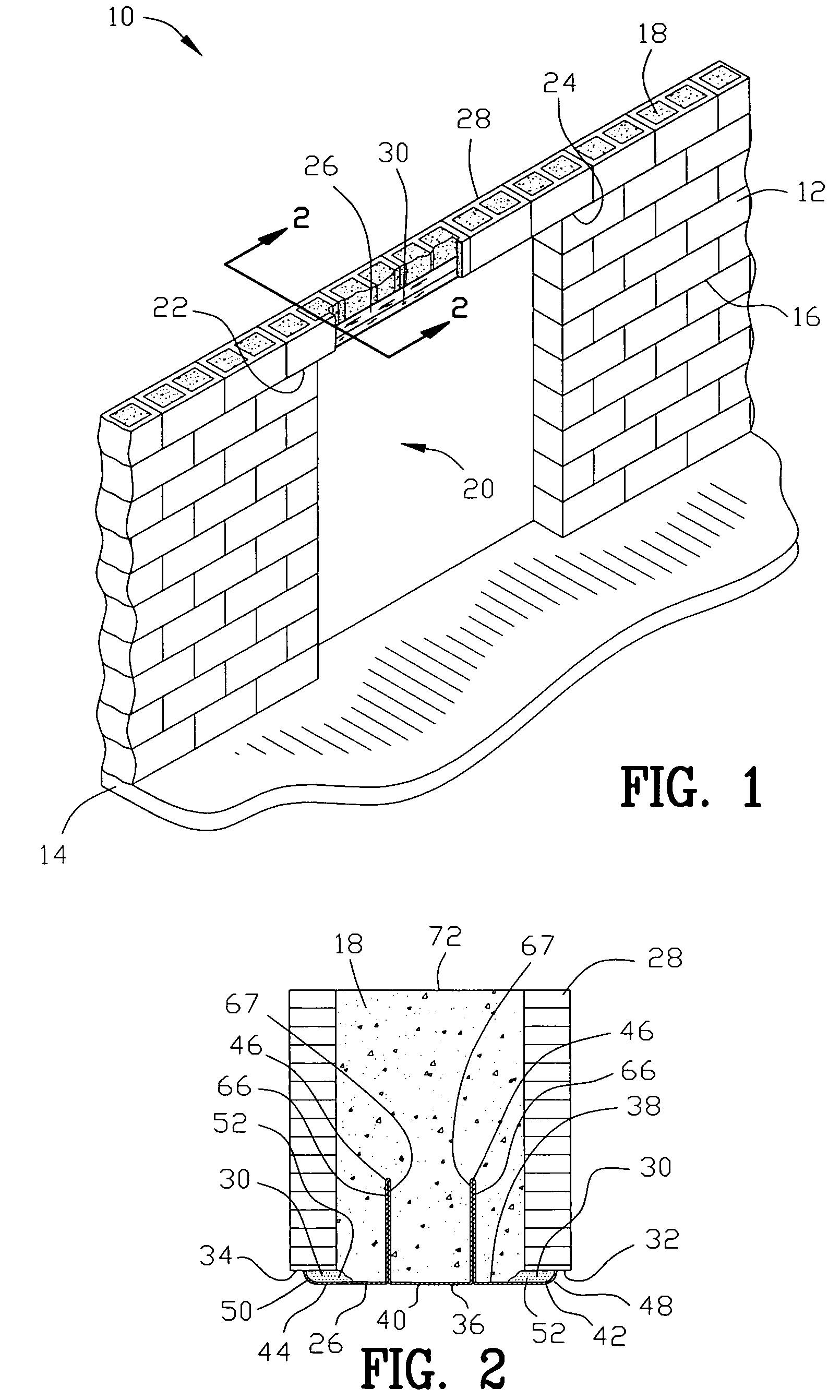
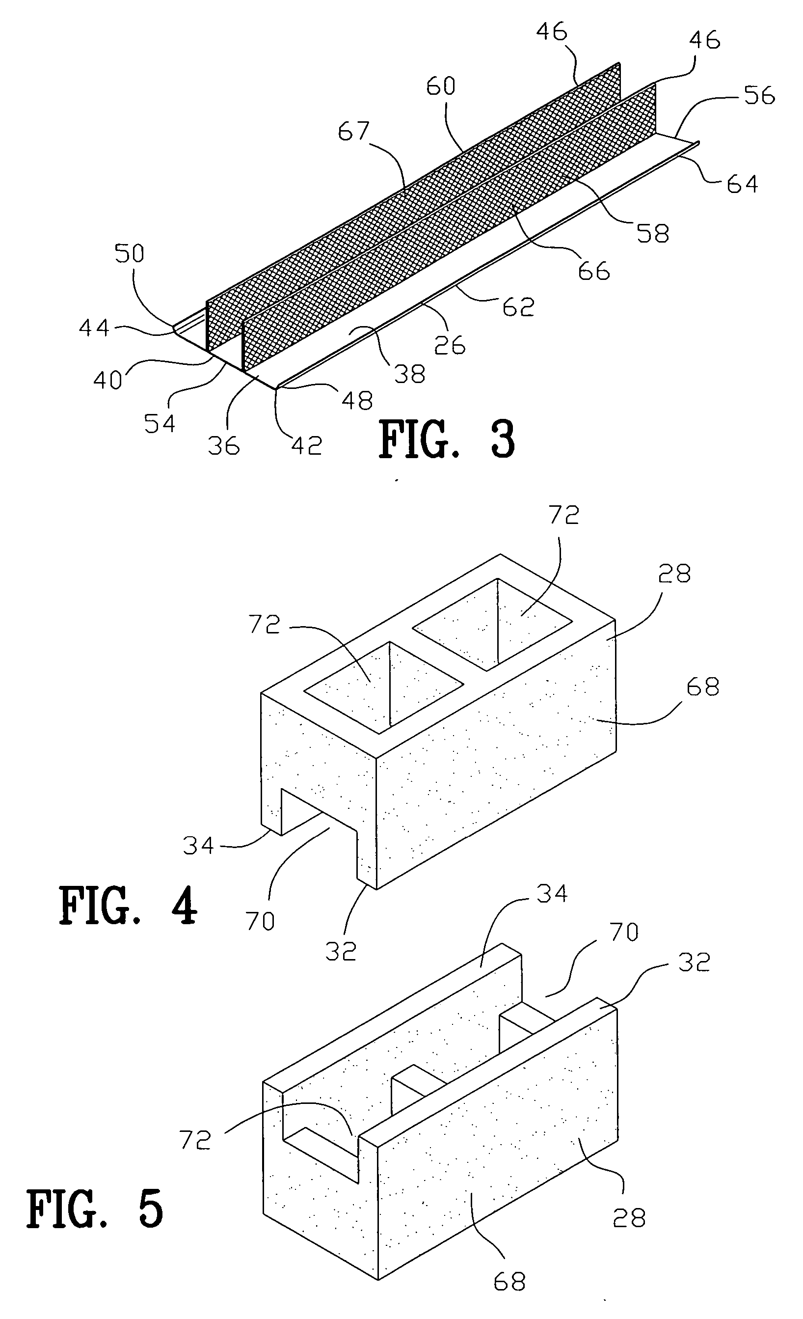
[0022] The lintel comprises an elongated base having a first end and a second end for extending between the first supporting surface and the second supporting surface. The elongated base has a top portion and a bottom portion, a first side and a second side. A riser extends from the top portion of the elongated base for increasing the load capacity of the lintel. A first dam extends upwardly from the first side of the elongated base for pooling the binder adjacent to the first dam. A second dam extends upwardly from the second side of the elongated base for pooling the binder adjacent to the second dam. The first and second bearing portions of the course of blocks are positioned above the first and second dams with the pooled binder supporting the first and secon

Problems solved by technology

Lintels constructed of stone resist weathering and corrosion, however a stone lintel may span only very limited distances due to the weight of the lintel and lack of tensile strength.
Lintels constructed from timber are capable of spanning further distances than stone lintels, however timber is susceptible to burning and decaying.
Concrete lintels may span f

Method used


Image

  • Lintel
  • Lintel
  • Lintel

Examples


second embodiment

[0063]FIGS. 6-11 illustrate a second embodiment for the improved invention 10. The riser has a proximal end 74 and a distal end 76. The proximal end 74 is secured to the top portion 38 of the elongated base 36. The distal end includes an enlarged flange 78 for increasing the load capacity of the lintel 26. Upon placement of the course of blocks 28 on the lintel 26, the elongated base 36 and first and second dam 48 and 50 will be in tension. The riser have a portion in tension and a portion under compression. The enlarged flange 78 is in compression. The enlarged flange 78 may contain the texture surface 66 including a series of grooves 67. The grooves 67 provide additional surface area for the grout 18 to bond to the lintel 26.

[0064] The cells 72 are filled with grout 18 to encase the lintel 26 and enlarged flange 78. After the grout has cured and a load is placed upon the lintel 26, the enlarged flange 78 is placed under a tensile force. The grooves 67 prevent movement of the enlar...

third embodiment

[0071]FIGS. 12-14 illustrate a third embodiment for the improved invention 10. A first guide riser 104 and a second guide riser 106 extend from the top portion 38 of the elongated base 36. The first and second guide risers 104 and 106 are disposed in a spaced apart parallel relationship between the first and second dams 48 and 50 for aligning the course of blocks 28 on the lintel 26. The first and second guide risers 104 and 106 are centered in relation to the width of the elongated base 26. The distance between the first and second guide risers 104 and 106 is commensurate with the width of the cell 72 such that upon placing the course of blocks 28 upon the lintel 26, the first and second guide risers 104 and 106 extend into the cell 72 to prevent horizontal movement of the course of blocks 28 relative to the lintel 26.

[0072]FIG. 12 is a sectional view of one of the course of blocks 28 and the lintel 26. In FIG. 12 the first and second guide risers 104 and 106 are disposed with a si...


PUM


Abstract

A lintel is disclosed for supporting a course of blocks with a binder above an opening. The opening is defined between a first supporting surface and a second supporting surface. The course of blocks include a first bearing portion and a second bearing portion. The lintel comprises an elongated base having a first end and a second end for extending between the first supporting surface and the second supporting surface. The elongated base has a top portion and a bottom portion, a first side and a second side. A riser extends from the top portion of the elongated base for increasing the load capacity of the lintel. A first dam extends upwardly from the first side of the elongated base for pooling the binder adjacent to the first dam. A second dam extends upwardly from the second side of the elongated base for pooling the binder adjacent to the second dam. The first and second bearing portions of the course of blocks are positioned above the first and second dams with the pooled binder supporting the first and second bearing portions of the course of blocks.

Description

BACKGROUND OF THE INVENTION [0001] 1. Field of the Invention [0002] This invention relates to lintels and more particularly to a new and improved lintel and method of supporting a course of blocks with a binder above an opening. [0003] 2. Background of the Invention [0004] A post-and-lintel construction is most often utilized for supporting a load above an opening. The post-and-lintel construction has been used all over the world and for centuries ranging from the stone circle at Stonehenge and the Greek architecture of the Parthenon in Athens to present day commercial and residential windows and doorways. Lintels have been constructed from stone, timber, concrete or steel. Each of these materials have positive and negative characteristics when used to construct a lintel. [0005] Lintels constructed of stone resist weathering and corrosion, however a stone lintel may span only very limited distances due to the weight of the lintel and lack of tensile strength. Lintels constructed fro...

Claims


Application Information

Patent Timeline
IPC IPC(8): E04C3/02
CPCE04C3/02E04C2003/023
Inventor PARRINO, CRAIG P.HUGHES, RALPH W.ROBB, CHARLES K.KARDASH, WILLIAM J.STANTON, JOHN D.
Owner CAST CRETE CORP
Why Eureka
Try Eureka