Glassware forming machine mold cooling apparatus and method

a technology of cooling apparatus and glassware, which is applied in the direction of glass tempering apparatus, glass rolling apparatus, manufacturing tools, etc., can solve the problems of reducing the air flow rate through the tube for a given source pressure, maintenance problems,

Inactive Publication Date: 2006-08-17
OWENS-BROCKWAY GLASS CONTAINER INC
View PDF12 Cites 9 Cited by
  • Summary
  • Abstract
  • Description
  • Claims
  • Application Information

AI Technical Summary

Problems solved by technology

Of course, the bushing that is partly telescoped into the outlet of the air flow conduit decreases its diameter at that location, and thereby serves as a cooling air flow obstruction to reduce the flow of cooling air to the molds for a given air pressure source.
Further, the use of a slide member at the inlet of the airflow conduit, which serves to accommodate spacing changes between the plenum to which inlet is attached and the mold carrying arm plenum to which its outlet is connected due to the oscillating motion of the mold carr

Method used


Image

  • Glassware forming machine mold cooling apparatus and method
  • Glassware forming machine mold cooling apparatus and method
  • Glassware forming machine mold cooling apparatus and method

Examples


Embodiment Construction

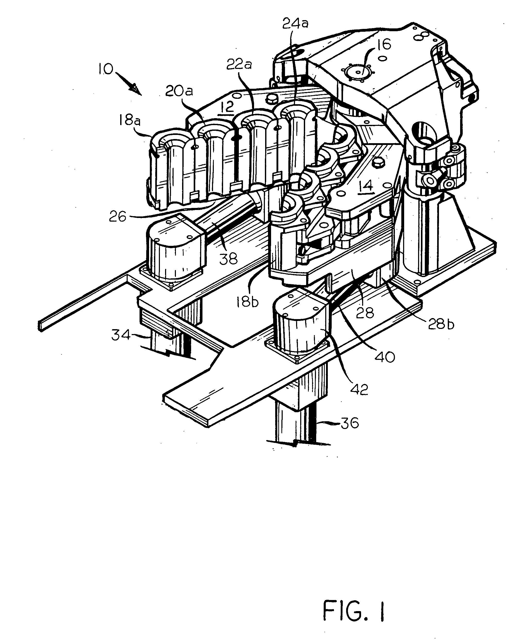
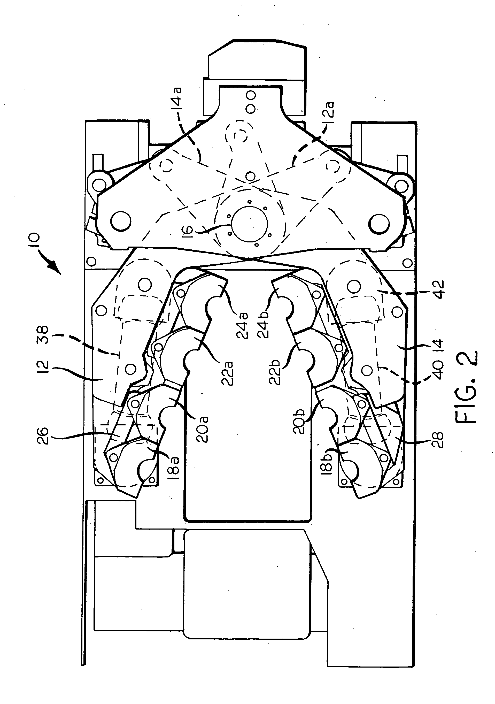
[0014] Apparatus according to an embodiment of the present invention is indicated generally by reference numeral 10 in FIGS. 1 and 2. The apparatus 10, which may be considered to be a portion of a glass container forming machine of the I.S. type at a blank side of the machine, is made up of-an opposed pair of mold carrying arms 12, 14 that are mounted for pivoting movement about a vertical shaft 16. The mold-carrying arms 12, 14 carry mold halves of one or more glass article forming molds, shown as four such mold halves 18a, 20a, 22a, 24a that are carried by the arm 12, and the mold halves 18b, 20b, 22b, 24b that are carried by the arm 14. The mold arms 12, 14 are caused to counter-oscillate about the shaft 16 by forces applied to their opposed ends 12a, 14a, respectively, for example, in the manner taught by U.S. Pat. No. 4,427,431 (Mumford et al.) or by U.S. Pat. No. 3,472,639 (Mumford), the disclosure of each of which is incorporated by reference herein, or as taught, for example...


PUM

PropertyMeasurementUnit
Angleaaaaaaaaaa
Temperatureaaaaaaaaaa
Thicknessaaaaaaaaaa

Abstract

In a blank mold side of an I.S. glass container forming machine, mold cooling air flows from a fixed source through a supply conduit to a plenum that underlies and oscillates with a mold-carrying arm. Cooling air from the source flows upwardly through the supply conduit and then into a hollow member that has an inlet portion telescopically received in an outlet of the supply conduit. The hollow member, which is capable of oscillating motion in a horizontal plane with respect to the supply conduit, has a horizontally-facing outlet with an annular part-spherical bearing surface, and an annular part-spherical bearing is positioned in the part-spherical bearing surface for pivoting motion in a vertical plane of the part-spherical bearing with respect to the hollow member. A cooling air inlet tube has an inlet end telescopically received in the part-spherical bearing. The outlet end of the cooling air inlet tube is non-telescopically received in a part-spherical bearing surface of the plenum. In a blow mold side of an I.S. glass container forming machine, cooling air flows from a fixed source through a supply conduit to a plenum that underlies and oscillates with a mold-carrying arm without any substantial change in the direction of air flow therethrough. A cooling air inlet tube having an outer element, an inner element telescopically positioned within the outer element and a spring to resiliently bias the inner element and the outer element away from one another is provided to accommodate changes in distance between the source and the plenum that occur because of oscillating motion of the mold-carrying arm.

Description

FIELD OF THE INVENTION [0001] This invention relates to a glassware forming machine of the individual section (I.S.) type in which one or more mold halves carried by each of an opposed pair of mold carrying arms are periodically oscillated into and out of closed positions to form closed molds. More particularly, this invention relates to the distribution of cooling air to the mold carrying arms to cool the mold halves, notwithstanding the movement of the mold halves relative to a source of cooling air due to the oscillating motion of the mold-carrying arms and the variation in the lengths of the cooling air flow paths that results therefrom. BACKGROUND OF THE INVENTION [0002] U.S. Pat. No. 4,909,823 (Bollin) and U.S. Pat. No. 5,304,229 (Swanfeld) relate to the distribution of cooling air from a windbox of an I.S. machine to opposed sets of mold halves. The mold halves are carried by opposed arms that are repeatedly oscillated or swung into and out of closed positions in which oppose...

Claims


Application Information

Patent Timeline
IPC IPC(8): C03B11/12C03B9/38C03B9/353
CPCC03B9/3532C03B9/3875C03B9/3891C03B9/00C03B9/38
Inventor DIFRANK, FRANK J.LEIDY, D. WAYNEKIRKMAN, THOMAS R.
Owner OWENS-BROCKWAY GLASS CONTAINER INC
Why Eureka
Try Eureka