
Installation with belt-like drive means and method for transmission of electrical energy or signals in such an installation

a technology of belt-like drive and transmission means, which is applied in the direction of elevators, transportation and packaging, building lifts, etc., can solve the problems of complex cable provision and mounting, difficult contact with the integrated conductor, and inconvenient installation of such elevators, so as to achieve reliable and simple installation

Inactive Publication Date: 2006-08-17
INVENTIO AG
View PDF8 Cites 14 Cited by
  • Summary
  • Abstract
  • Description
  • Claims
  • Application Information

AI Technical Summary

Benefits of technology

[0005] It is therefore an object of the present invention to offer a reliable and simple installation as well as a method enabling transmission of energy and / or signals by way of different kinds of belt-like drive means. It is regarded as a further object of the present invention that the assembly of such an installation shall be simplified and able to be carried out without problems. A further object resides in providing an economic solution for energy and signal transmission in such an installation.
[0007] An installation according to the present invention has the following advantages:
[0008] The use of belt-like drive means, which are driven by drive pulleys by means of friction couple, permits a predeterminable limitation of the maximum arising traction force by selection of the friction materials and the looping angle at the drive pulley. In installations in which the possibility exists of the object moved by the drive means being blocked, damage and risks to persons can thereby be avoided.
[0009] In elevator installations the friction-locking transmission of traction force to the drive means has the effect that, for example, the elevator car is no longer raised when the counterweight in the case of a control failure moves onto its lower travel limitation, whereby a safety risk is eliminated. It is thus also achieved that the drive unit is not abruptly stopped if the car or the counterweight moves onto its travel limitation, whereby overloads of the entire drive are avoided.
[0010] Belt-like drive means, which are driven by friction couple by drive pulleys, are generally simpler and more economic to produce than cogged belts.
[0011] In the case of, for example, elevator installations the use of drive means, acting by friction couple, with integrated electrical conductors instead of a toothed drive means makes it possible to dispense with installing a hanging cable for transmission of energy and / or signals. Costs for the material outlay are thereby reduced and the assembly of the installation simplified. Moreover, problems which can arise due to unguided suspension cables, which are therefore susceptible to oscillation, are eliminated.

Problems solved by technology

Disturbances can occur in such elevator installations when the cables are damaged.
Moreover, provision and mounting of the cables is complicated in some circumstances.
In that case, however, contact-making with the integrated conductors is difficult, since the current transfer has to be carried out from a stationary location to the conductors embedded in the drive means, while the drive means are moving past this stationary location.
A disadvantage of this approach is that it can be used only in the case of cogged belts.
A further disadvantage is that the drive pulley, which is already a complex and costly component of an elevator installation, is still more complex due to the mounting of the contacts.
Intervention in the region of the tooth gaps leads to weakening of the cogged belt and in the worst case can even impair the load-bearing capability of the belt.

Method used


Image

  • Installation with belt-like drive means and method for transmission of electrical energy or signals in such an installation
  • Installation with belt-like drive means and method for transmission of electrical energy or signals in such an installation
  • Installation with belt-like drive means and method for transmission of electrical energy or signals in such an installation

Examples


first embodiment

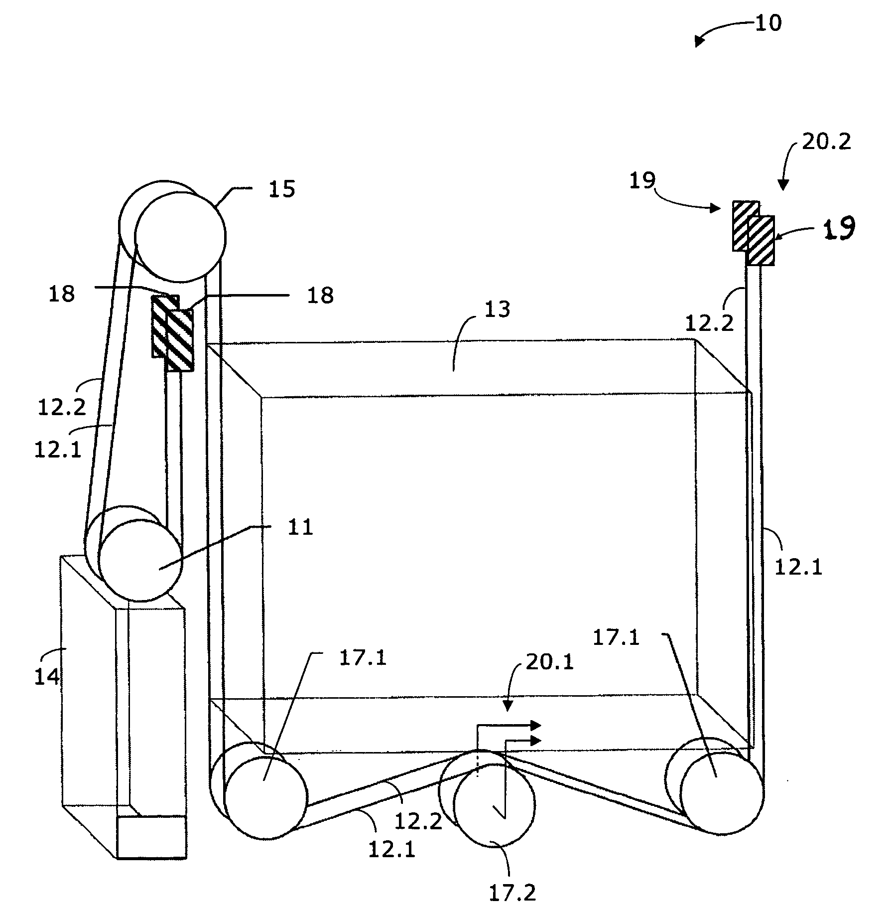
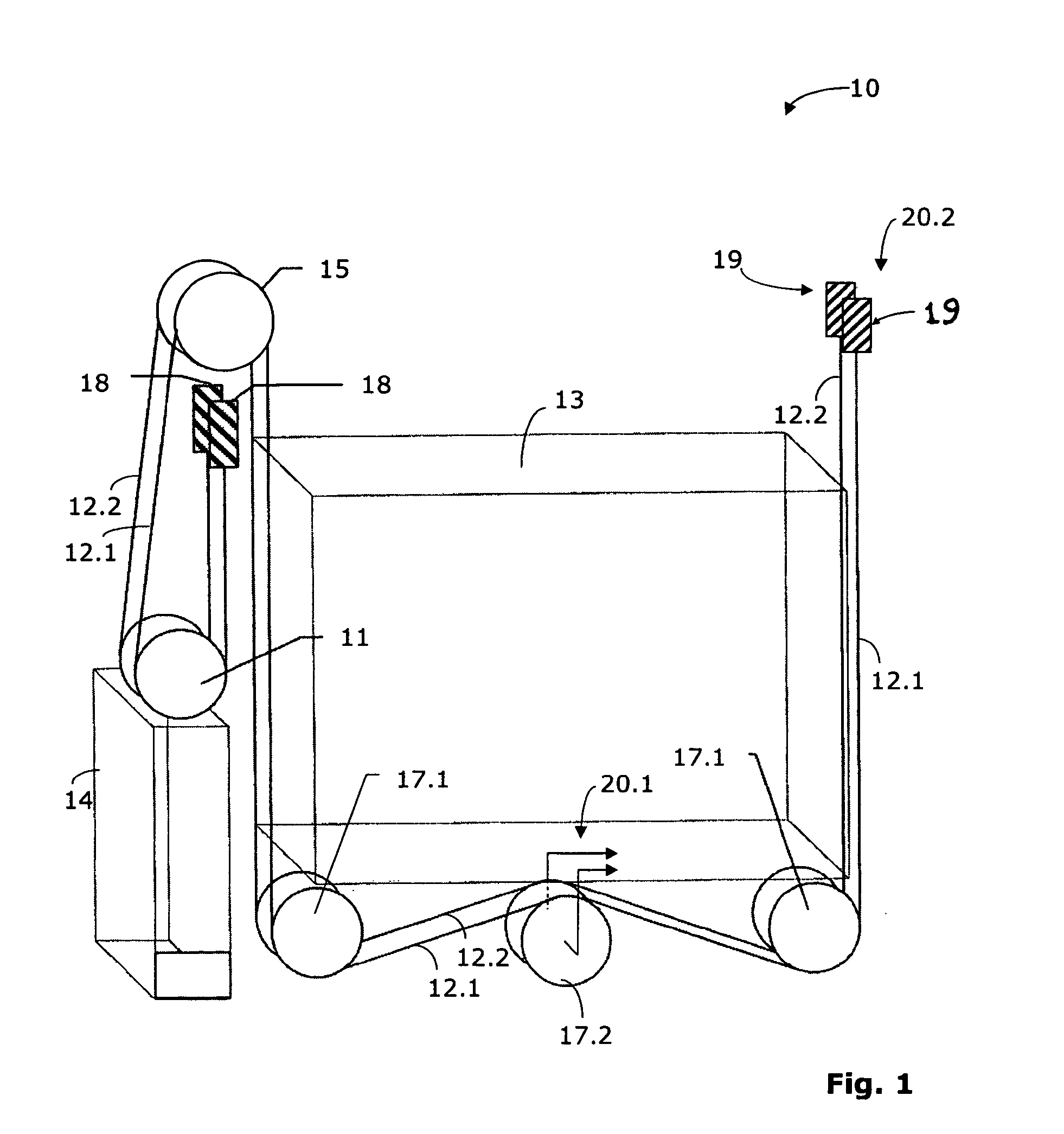
[0029] the present invention is illustrated in FIG. 1. In the case of the example shown in FIG. 1, this is an elevator installation 10 which does not have an engine room and which comprises an elevator car 13. Two drive means 12.1, 12.2 are provided, which extend substantially parallel to one another. In the following description and in FIG. 1 the front drive means is denoted by 12.1 and the rear drive means by 12.2 where this is necessary for better distinction. The ends of the drive means 12.1, 12.2 at the car side are fixed in the region of first drive means fixing points 19 to a guide rail or to an elevator shaft. Each of the drive means 12.1 and 12.2 loops under the elevator car 13, loops around a drive pulley 15 which is connected with a drive unit (not visible in FIG. 1), and carries a counterweight 14. In the illustrated example the drive means 12.1, 12.2 carry the counterweight 14 in that the drive means 12.1, 12.2 run around counterweight rollers 11 and are fixed at the en...

second embodiment

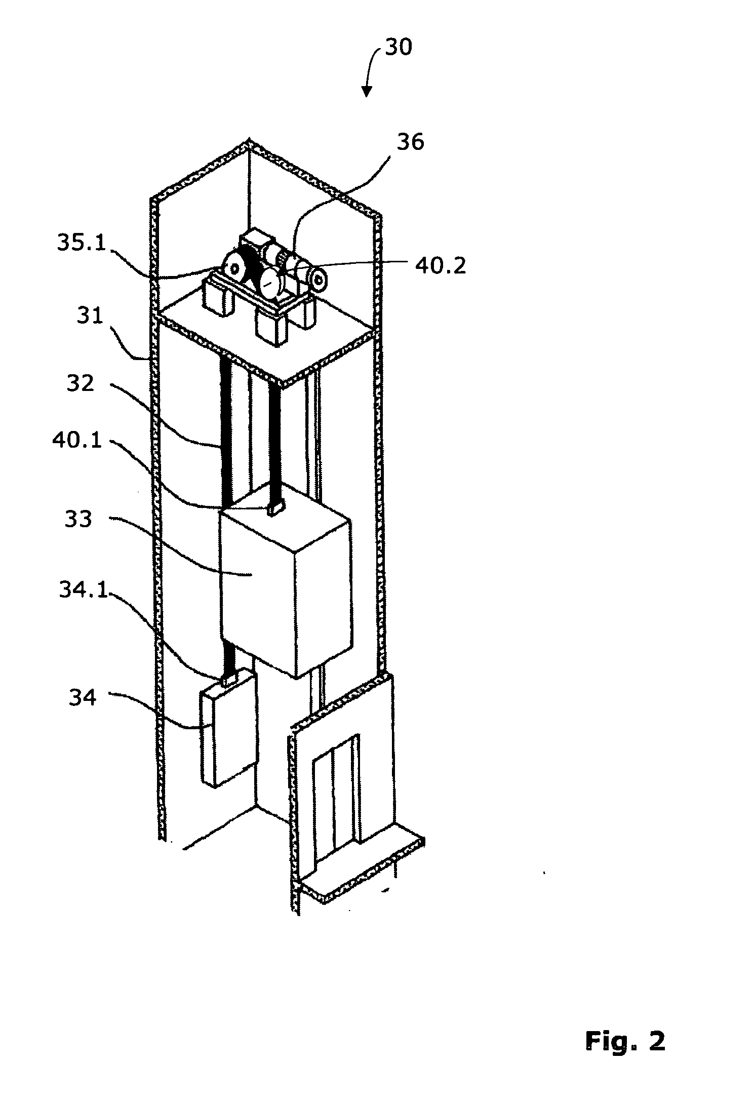
[0034] A further or second embodiment of the present invention is now described in connection with FIG. 2. An elevator installation 30 with a belt-like drive means 32 is shown, which is driven by a drive unit 36 by way of a drive pulley 35.1 in order to move an elevator car 33 in a schematically indicated elevator shaft 31. At least one electrically conductive element for transmission of signals and / or energy is provided in the drive means 32. This electrically conductive element extends along the longitudinal direction of the drive means 32. Contact means 40.2 are provided in the region of the drive means 32. The drive means 32 move relative to these contact means 40.2.

[0035] At least one groove, which extends parallel to the longitudinal direction of the drive means 32, is provided at the drive means 32. The groove is so formed that it enables access of the contact means 40.2 to the at least one electrically conductive element. The contact means 40.2 are so constructed and, with r...


PUM


Abstract

An installation, such as an elevator installation, has a belt-like drive apparatus driven by friction couple with a drive pulley. The drive apparatus has at least one electrically conductive element extending in a longitudinal direction of the drive apparatus. During operation of the installation, a contact apparatus contacts the at least one electrically conductive element of the moving drive apparatus for transmission of signals and / or electrical energy.

Description

BACKGROUND OF THE INVENTION [0001] The present invention relates to an installation with a belt-like drive means. [0002] Such installations are typically elevator installations which are equipped with so-termed hanging cables in order to supply an elevator car with current or in order to transmit signals between the elevator car and a control. Disturbances can occur in such elevator installations when the cables are damaged. Moreover, provision and mounting of the cables is complicated in some circumstances. Hanging cables are also used in other installations, such as, for example, crane installations and the like. [0003] According to German Patent Specification DE 10232965 there is recently a move towards replacing hanging cables in that use is made of drive means which have integrated conductors. In that case, however, contact-making with the integrated conductors is difficult, since the current transfer has to be carried out from a stationary location to the conductors embedded i...

Claims


Application Information

Patent Timeline
Patent Type & Authority Applications(United States)
IPC IPC(8): B66B11/08
CPCB66B1/34B66B1/3415B66B1/3446B66B7/06B66B7/062B66B7/064
Inventor SILBERHORN, GERTKEISER, DANIELBAUMGARTNER, URS
Owner INVENTIO AG
Learn More