MEM's reed switch array

a micro electromechanical system and array technology, applied in the direction of instruments, relays, burglar alarm mechanical actuation, etc., can solve the problems of affecting the operation of the high-security switch, the array of form a and c reed switches is much larger and significantly more expensive, and the reed switch is more expensive. , to achieve the effect of small size, increased range of sensitivity, and low cost of manufactur

Active Publication Date: 2006-08-17
ADEMCO INC
View PDF2 Cites 10 Cited by
  • Summary
  • Abstract
  • Description
  • Claims
  • Application Information

AI Technical Summary

Benefits of technology

[0009] Therefore, it is an object of the present invention to provide a MEM's reed switch array that has a smaller size, an incr

Problems solved by technology

This arrangement can be compromised by introducing a magnetic field with the same pole orientation as the magnet used in the assembly.
High security switches utilize arrays of form A and C reed switches and are much larger and significantly more expensive.
The tighter th

Method used


Image

  • MEM's reed switch array
  • MEM's reed switch array
  • MEM's reed switch array

Examples


Embodiment Construction

[0028] Although this invention may be applicable to various uses of reed switch arrays, it has been found particularly useful in the environment of alarm systems for commercial and residential structures. Therefore, without limiting the applicability of the invention to the above, the invention will be described in such environment.

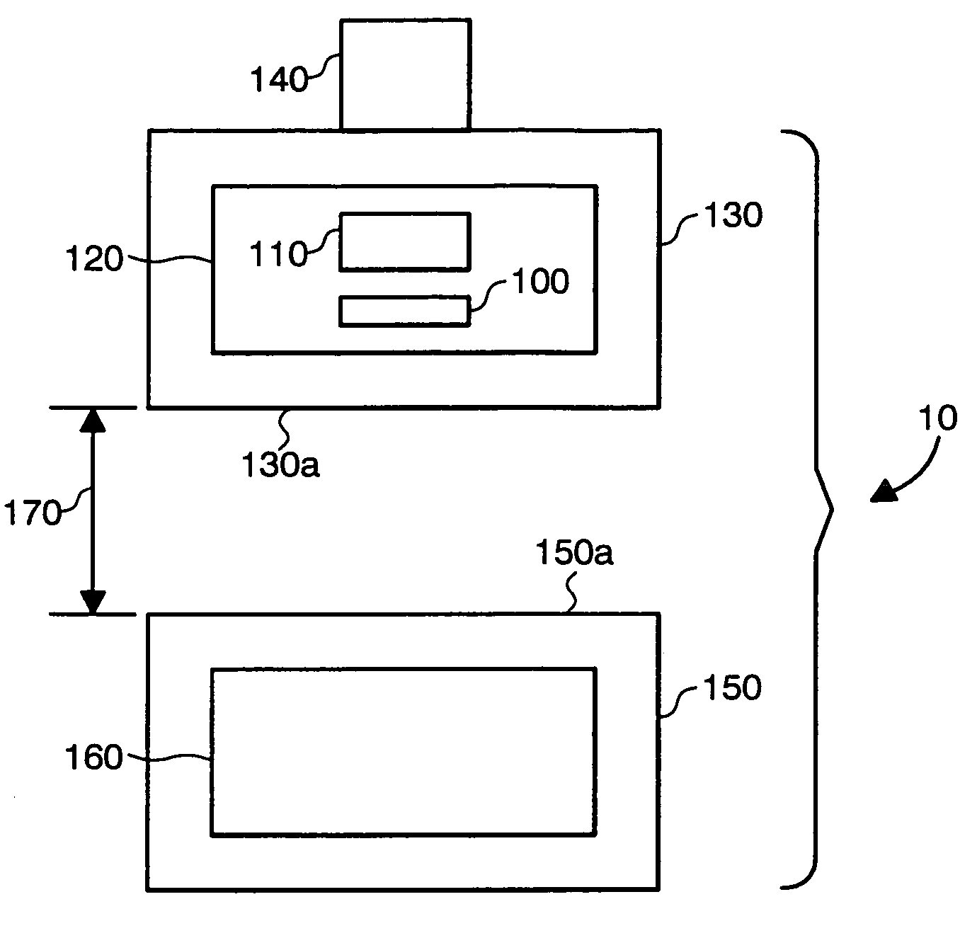
[0029] With reference now to the drawings, the components of the present invention will be described. In FIG. 1, a device 10 is shown comprising a magnet housing 150 and a switch housing 130. The distance between an outer surface 130a of the switch housing 130 and an outer surface 150a of the magnet housing 150 is referred to as a gap 170.

[0030] The magnet housing 150 contains a magnet 160 and an attachment means (not shown) for attaching it to a door or window. The magnet housing 150 can be constructed of any material such as plastic, aluminum, or other non-ferrous metal such as is used in contacts designed for garage doors or high security switches th...


PUM


Abstract

A MEM's reed switch array is provided having a first switch having a sensitivity causing the first switch to open or close due to a magnetic flux, and a second switch of lesser sensitivity than the first switch causing the second switch to open or close due to a magnetic flux. The first switch can be parallel to the second switch, or the first switch can be proximate to the second switch so that a center line of the first switch is coaxial to a center line of the second switch. Further, a security device for residential and/or commercial use is provided, having a magnet housing having a magnet, a switch housing having a MEM's reed switch array with a first switch and a second switch, and a gap between the magnet housing and the switch housing.

Description

BACKGROUND OF THE INVENTION [0001] 1. Field of the Invention [0002] The present invention relates to reed switch arrays, and more specifically, to a micro electromechanical systems (MEM's) reed switch array. [0003] 2. Prior Art [0004] Reed switches are magnetically actuated switches, which are typically manufactured with two ferromagnetic reeds (contact blades) spaced a distance apart, which are sealed in a glass capsule. In the presence of a magnet, the blades (contacts) are deflected until they contact. This arrangement can be compromised by introducing a magnetic field with the same pole orientation as the magnet used in the assembly. [0005] Reed switch types consist of dry reed or mercury wetted reed switches. A dry reed switch contains ferromagnetic contact blades sealed in a glass container with an inert gas. In a mercury wetted reed switch, mercury is the contact material for an electrical circuit. The contacting faces are renewed by capillary action drawing a film of mercury...

Claims


Application Information

Patent Timeline
IPC IPC(8): H01H51/22
CPCH01H36/0046H01H2036/0093
Inventor LEE, ROBERT E.ESKILDSEN, KENNETH G.PIEL, KEVIN G.
Owner ADEMCO INC
Why Eureka
Try Eureka