Compensating liquid delivery system and method

a liquid delivery system and liquid technology, applied in liquid/fluent solid measurement, process and machine control, instruments, etc., can solve the problems of inaccurate measurement, large quantity of fluid moved each pump cycle, and relatively tight manufacturing tolerances, etc., to achieve accurate measurement

Inactive Publication Date: 2006-08-17
SAGE BURTON H JR
View PDF5 Cites 89 Cited by
  • Summary
  • Abstract
  • Description
  • Claims
  • Application Information

AI Technical Summary

Benefits of technology

[0023] The infusion set is coupled to the reusable component such that fluid in the flow path may be observed by the flow sensor in the reusable component and the memory containing information related to the flow path may be read by the reader. The inlet end of the infusion set is connected to the fluid supply. The system is then primed such that the infusion set is filled with the fluid and flow is stopped. Then the cannula at the outlet end is placed in the vein. The desired flow protocol for administering the fluid to the patient is entered through the interface and the protocol is implemented. The processor causes the pump driver to begin delivery of the fluid through the infusion set by taking at least one pumping action. During the pumping action, the flow sensor records at least one property of flow at least once, but typically many times. Typically, the flow sensor measures a velocity of the fluid, but may alternatively measure volumetric flow rate. The flow sensor makes sufficient measurements of the flow such that the volume of fluid delivered by the pumping action is accurately measured. Depending on the rate of change of flow rate, the sensor may be capable of measuring flow rate up to several thousand times per second. The processor then combines the measured delivered fluid volume and the current rate of pumping actions to calculate the current actual fluid delivery rate. This actual fluid delivery rate is then compared to the desired fluid delivery rate, and the timing of the next pump driver action is adjusted such that if the measured fluid delivery rate is higher than the desired fluid delivery rate, the time until the next pump action is lengthened and if the measured fluid delivery rate is lower than the desired fluid delivery rate, the time until the next pump driver action is shortened.

Problems solved by technology

Such gravity bag infusion, while able to provide the medical liquid to the patient in a continuous fashion, suffered from accuracy problems.
Again, the delivery accuracy depends on the inside diameter of the flow tube to the second power, so manufacturing tolerances are relatively tight.
Further, with peristaltic pumps during use, as the flow tube is repeatable compressed to move the fluid along the tube, the dimensions of the tube change causing the quantity of fluid moved each pump cycle to slowly change over time.
Also, if system components are used that are outside of the specification range, such positive displacement systems will inaccurately deliver the medical liquid.
Since these systems are “open-loop”, these changes are not recognized and the pump continues to deliver fluid at an improper rate.
This closed loop system, however, fails to distinguish between changes in flow rate due to temperature, viscosity, or flow channel dimensions.
Because the flow rate has differing exponential dependence for these flow rate variables, the calculated valve adjustment does not completely correct the flow rate discrepancy, resulting in incompletely corrected infusion of the medical liquid.
However, this system is limited to pressurized fluid supply reservoirs, and does not describe the methods appropriate for compensating for the variability in system components that arise either from manufacture or use in positive displacement fluid delivery system.
While representing a significant improvement over simple and inexpensive gravity bags, complicated and expensive infusion pumps still typically fail to achieve highly accurate delivery over the course of desired infusion, or to provide evidence that the desired drug delivery is occurring or has occurred (other than that the motor is operating or has operated).

Method used


Image

  • Compensating liquid delivery system and method
  • Compensating liquid delivery system and method
  • Compensating liquid delivery system and method

Examples


Embodiment Construction

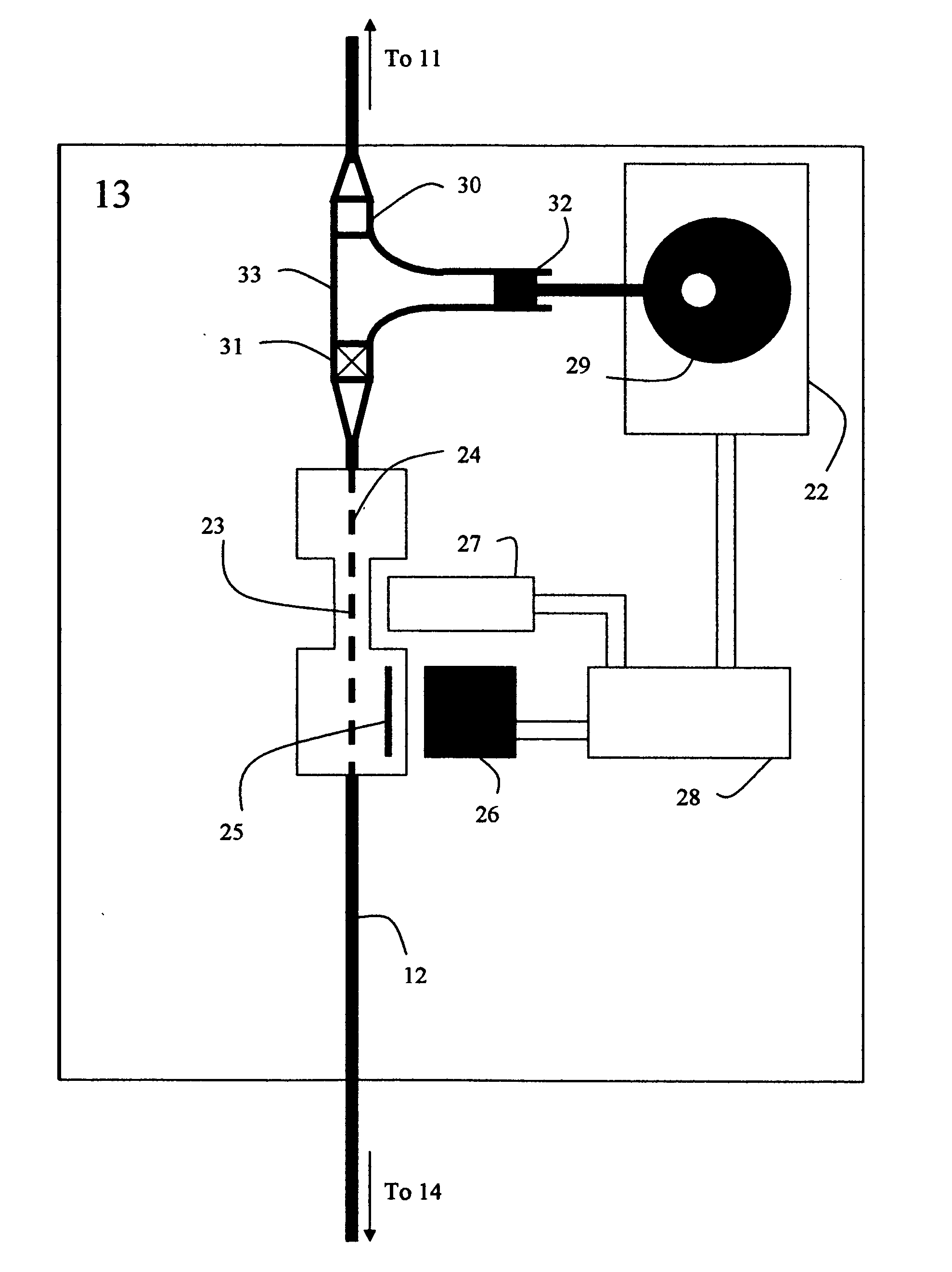
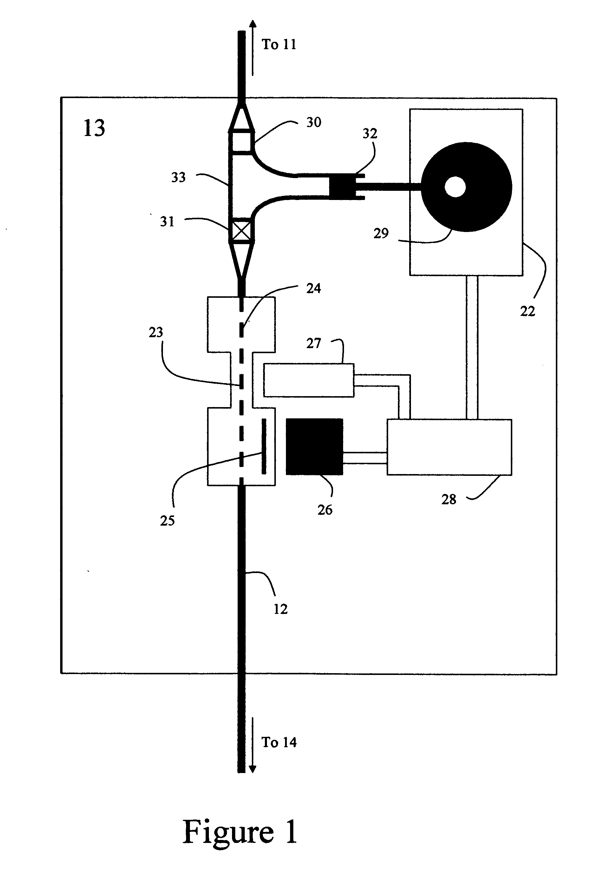
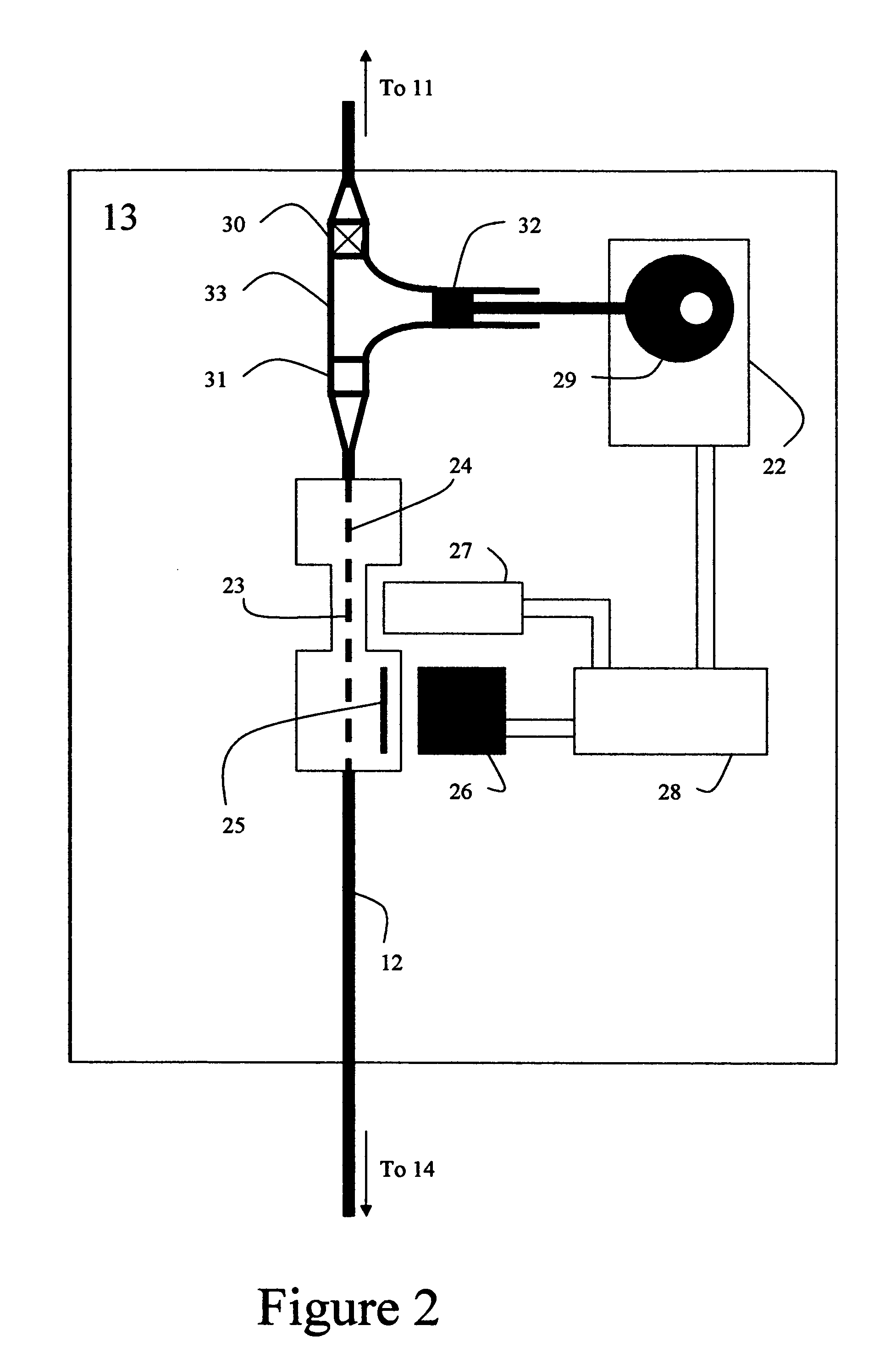
[0033] A first embodiment of the invention shows fluid supply system 13 in FIG. 1. Fluid enters flow path 12 from fluid supply container 11 (not shown). The fluid from supply container 11 enters the system 13 through valve 30 of pump 33. As shown, pump 33 has drawn fluid into its body through valve 30 since valve 30 is open. Since valve 31 is closed, this fluid remains in the pump awaiting the next pumping action. Pump 33 is under the control of pump driver 22 which is designed to rotate cam 29 to move piston 32. Processor 28 provides pumping instructions to driver 22. Also providing input to processor 28 is sensor 27, which measures at least one property of fluid flow along flow path 24 in interrogation region 23, and reader 26, which reads at least one property of interrogation region 23 stored in memory 25. The property of flow measured by sensor 27 is for example stream velocity as expressed in distance per time. Flow sensor 27 may operate by a number of different mechanisms suc...


PUM


Abstract

A compensating fluid supply system that is capable of near real time adjustment of the timing of a pumping action of a positive displacement pump is disclosed. The geometrical characteristics of a flow tube and a velocity of a moving stream are used to measure individual pumping actions. Based on the actual measured volume of fluid supplied with a pumping action and the desired supply rate of the fluid supply system, the timing of future pumping actions is determined.

Description

[0001] This application claims subject matter disclosed in co-pending application Ser. No. 10 / 662,871 filed Oct. 13, 2003. The content of this document is incorporated herein in its entirety by reference. FIELD OF THE INVENTION [0002] This invention relates generally to fluid delivery systems and more particularly to liquid supply systems for use in drug delivery. BACKGROUND OF THE INVENTION [0003] Accurate delivery of liquids, particularly in the field of infusion of medical liquids continues to be an important need. See, for example, Simmons, et al “An Adaptive Drug Infusion System”, Diabetes Technology and Therapeutics 6:5 p 607-20 (November, 2004), the content of which is incorporated herein in its entirety by reference. In IV infusion of pharmaceuticals, accurate infusion of therapeutic solutions is becoming more and more critical as the potency of infusible therapeutic agents continues to increase and the volumes of fluids decrease. This need is especially critical in neonatal...

Claims


Application Information

Patent Timeline
Patent Type & Authority Applications(United States)
IPC IPC(8): G01P3/36G01F1/7084G01F1/7086
CPCA61M5/14216A61M5/172A61M2205/3306A61M2205/3331G01F1/7084G05D7/0676G01F1/7086
Inventor SAGE, BURTON H. JR.
Owner SAGE BURTON H JR
Why Eureka
Try Eureka