Light scanning device and image display apparatus

a light scanning device and image display technology, applied in the field of light scanning devices and image display apparatuses, can solve the problems of deteriorating image quality, difficult to regenerate a new image signal corresponding, and the difficulty of the light scanning device to scan the laser beam to a correct position

Inactive Publication Date: 2006-08-17
SEIKO EPSON CORP
View PDF14 Cites 23 Cited by
  • Summary
  • Abstract
  • Description
  • Claims
  • Application Information

AI Technical Summary

Benefits of technology

[0019] It is preferable that an axis of rotation for oscillating the reflection mirror so as to allow the light beam to be scanned in the first direction is provided and the reflection mirror corrects the position of the light beam to be scanned by adjusting at least one of the shape of the axis of rotation and the position to provide the axis of rotation. Adjustment of the shape of the axis of rotation is achieved, for example, by differentiating the thickness or the length of the axis of rotation. Adjustment of the position to provide the axis of rotation is achieved, for example, by providing the axis of rotation at a position different from a centerline of the reflection mirror. In this manner, the state in which the reflection mirror can resonate so as to allow the light beam to be scanned in the direction different from the first direction can be created. Accordingly, the reflection mirror can be resonated as to allow the light beam to be scanned in the direction different from the first direction.
[0020] According to a third aspect of the invention, an image display apparatus including the aforementioned light scanning device wherein an image is displayed on a predetermined surface by the light beam from the light scanning device is provided. With the aforementioned light scanning device, the light beam can be scanned accurately corresponding to the two-dimensionally arranged pixels. Accordingly, the image display apparatus which can display high-quality images is provided.

Problems solved by technology

When inclination or deflection of the mirror occurs, it is difficult for the light scanning device to scan the laser beam to a correct position.
When printing or displaying an image in which pixels are arranged two-dimensionally in a matrix manner, the displacement may result in quality deterioration of the image.
In addition, it is difficult to regenerate a new image signal corresponding to the incoming position of the laser beam in order to correct the displacement of the position of the laser beam.
However, provision of two scanning devices in one light scanning device may result in increase in size of the light scanning device.
Also, since provision of the two mirrors may complicate the structure and make adjustment of optical axis difficult, the manufacturing cost may increase.
In this manner, there is a problem that it is difficult to scan the laser beam accurately corresponding to the arrangement of pixels when the laser beam is scanned in the two-dimensional direction even with the technique in the related art.

Method used


Image

  • Light scanning device and image display apparatus
  • Light scanning device and image display apparatus
  • Light scanning device and image display apparatus

Examples


first embodiment

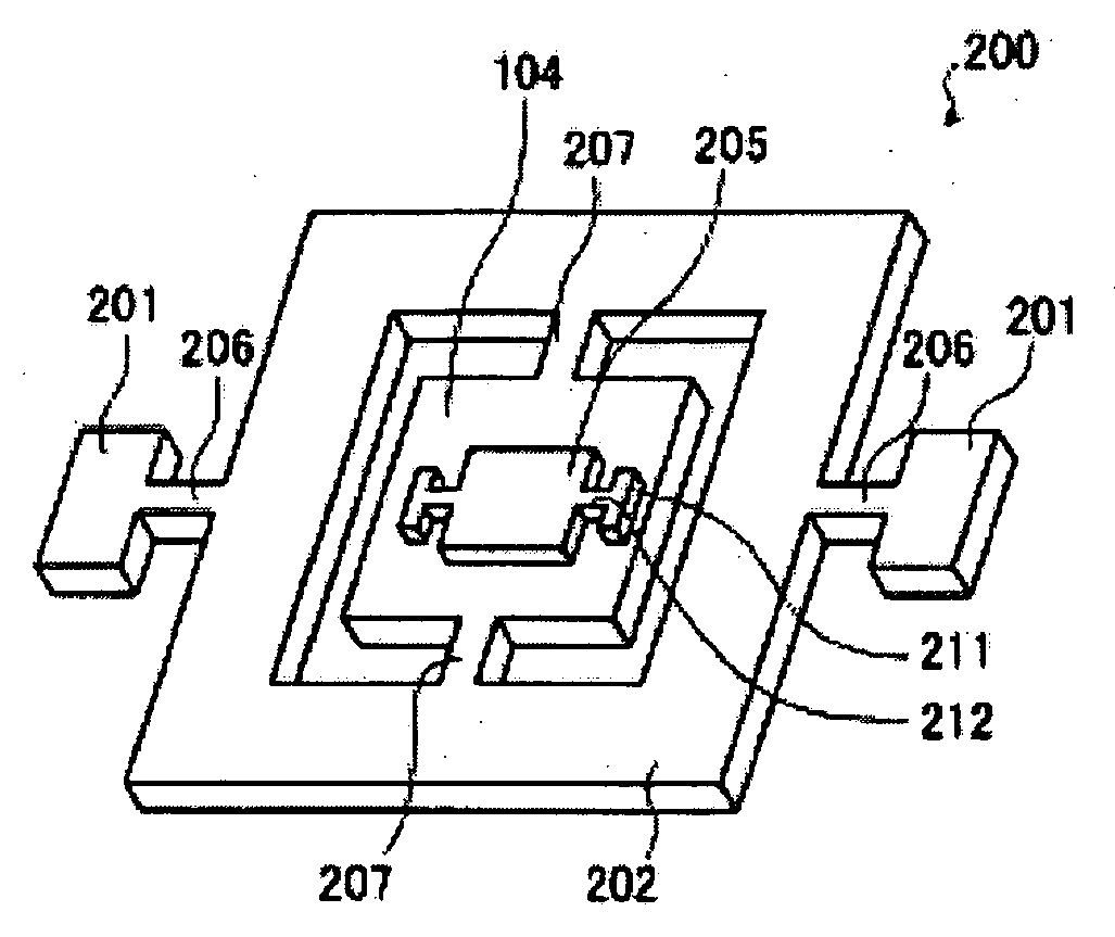
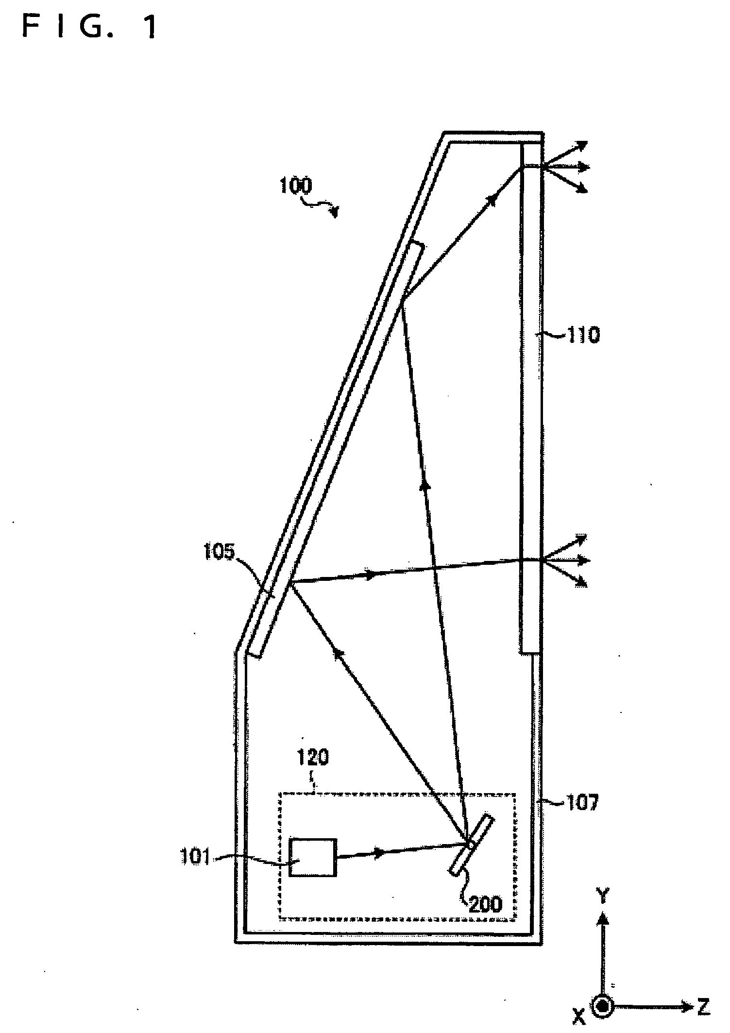
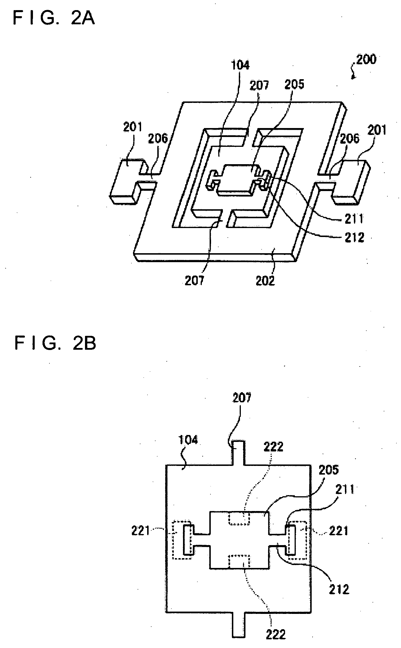
[0041]FIG. 1 shows a schematic drawing of an image display apparatus 100 according to a first embodiment of the invention. The image display apparatus 100 is a so-called rear projector configured in such a manner that a laser beam is supplied on one of the surfaces of a screen 110 and a viewer observes the light beam emitted from the other surface of the screen 110 to see an image. A light scanning device 120 provided in the image display apparatus 100 causes the laser beam to be scanned by a scanning unit 200. The image display apparatus 100 displays the image on the screen 110 surface which is a predetermined surface by the light beam from the light scanning device 120.

[0042] A light source 101 supplies a red laser beam, a green laser beam, and a blue laser beam, as light in the form of a beam, after having modulated according to image signals. The light source 101 may employ a semiconductor laser or a solid laser provided with a modulating section for modulating the laser beam. ...

second embodiment

[0073]FIG. 9 is an explanatory drawing showing the positional correction of the laser beam with the light scanning device according to a second embodiment of the invention. The light scanning device of this embodiment can be applied to the image display apparatus 100 according to the above-described first embodiment. Description of the portions overlapped with those in the first embodiment will be omitted. In the first embodiment, the reflection mirror is provided on the movable member connected to the outer frame. In contrast, this embodiment is characterized in that the position of the light beam to be scanned is corrected by the reflection mirror connected to the outer frame.

[0074] A graph shown in FIG. 9 represents the amplitude on the axis of ordinate and the frequency on the axis of abscissas, and illustrates an example of the amplitude of the reflection mirror with respect to the driving frequency. The reflection mirror is displaced so as to reflect the laser beam from the l...

third embodiment

[0090]FIG. 17 shows a schematic structure of an image display apparatus 1700 according to the third embodiment of the invention. Parts identical to those in the first embodiment are represented by the identical reference numerals, and overlapped description is omitted. The image display apparatus 1700 is a so-called front projecting type projector which supplies the laser beam to a screen 1705 provided on the viewer's side and a viewer observes the light beam reflected on a screen 1705 to see the image. The image display apparatus 1700 has the light scanning device 120 as in the first embodiment.

[0091] A light-emitting window 1710 formed of a transparent material such as glass or transparent resin is provided on the surface of the image display apparatus 1700 on the viewer's side. The laser beam from the light scanning device 120 passes through the light-emitting window 1710 and then enters the screen 1705. By employing the light scanning device 120, the laser beam can be scanned a...


PUM


Abstract

A light scanning device including: a light source that supplies light in the form of a beam; a reflection mirror that reflects the light beam from the light source; and a movable member that is provided integrally with the reflection mirror and displaces the light beam reflected from the reflection mirror so as to be scanned in a first direction and in a second direction substantially orthogonal to the first direction, the movable member being displaced so that a frequency to scan the light beam in the first direction is higher than the frequency to scan the light beam in the second direction, the reflection mirror being displaced not only in association with the movable member but also for allowing the light beam to be scanned in a direction different from the first direction and correcting the position of the light beam to be scanned in accordance with displacement of the movable member.

Description

BACKGROUND [0001] 1. Technical Field [0002] The present invention relates to a light scanning device and an image display apparatus and, more specifically, to a technique relating to a light scanning device that displays an image by scanning a laser beam modulated according to image signals. [0003] 2. Related Art [0004] A laser printer or a display device that displays an image by scanning a laser beam employs a light scanning device that scans the laser beam. The light scanning device changes the direction of travel of the laser beam from a light source by displacing a reflection mirror that reflects the laser beam. Scanning of the laser beam may be achieved, for example, by a polygon mirror that rotates a plurality of reflection mirrors. Since high-speed printing by the laser printer and high-resolution image display on the display device are increasingly required, the light scanning device is required to be able to scan the light beam at high speeds correspondingly. In order to s...

Claims


Application Information

Patent Timeline
Patent Type & Authority Applications(United States)
IPC IPC(8): G02B26/08
CPCG02B26/0833
Inventor YAMAZAKI, TETSURO
Owner SEIKO EPSON CORP
Why Eureka
Try Eureka