Molded washer assembly

Inactive Publication Date: 2006-08-17
UNDERWOOD J LARRY +1
View PDF28 Cites 15 Cited by
  • Summary
  • Abstract
  • Description
  • Claims
  • Application Information

AI Technical Summary

Benefits of technology

[0009] A washer of the present invention can be formed of an engineering plastic and has two substantially identical C-shaped sections, each section having parallel upper and lower surfaces and a perimeter comprising two ends, an inside arcuate edge and an outside arcuate edge. The ends include a plurality of tabs and recesses configured so that adjoining ends of the two sections inter-digitate to form a substantially continuous surface. The shape of the tabs and recesses can be selected so that the inter-digitation can be achieved without requiring any change in the thickness of the washer. Surface features in the nature of a substantially circumferential gro

Problems solved by technology

Often mechanical structures and equipment that include coupled elements, which are designed for some relative movement and have been used for some time, develop an undesirable wobble or play between the coupled elements.
While a washer can be constructed in accordance with this design when unrestricted by any other mechanical structures, the insertion of two such sections between two wobbling coupled elements becomes problematic particularly if the internal radius of the two semi-cylindrical sections closely approxima

Method used


Image

  • Molded washer assembly
  • Molded washer assembly
  • Molded washer assembly

Examples


Embodiment Construction

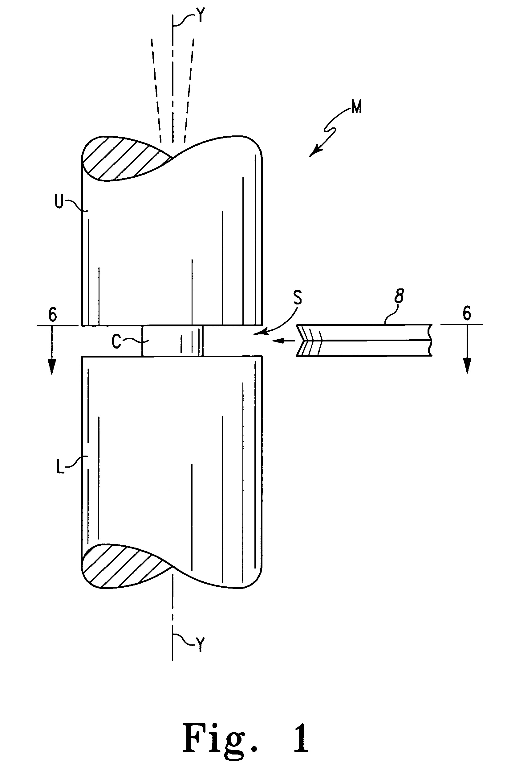
[0024]FIG. 1 shows a mechanical structure M consisting generally of an upper element U and a lower element L coupled together by a coupling C. The coupling C is surrounded by a space S. Assuming that the elements U and L are capable of some independent movement, the space S is sufficient to allow some wobble or play to develop between the elements as indicated by the variation in orientation of the upper element U with respect to the axis Y. This opportunity for wobble or play can be significantly reduced or eliminated by the insertion of a washer 8 of the present invention into the space S.

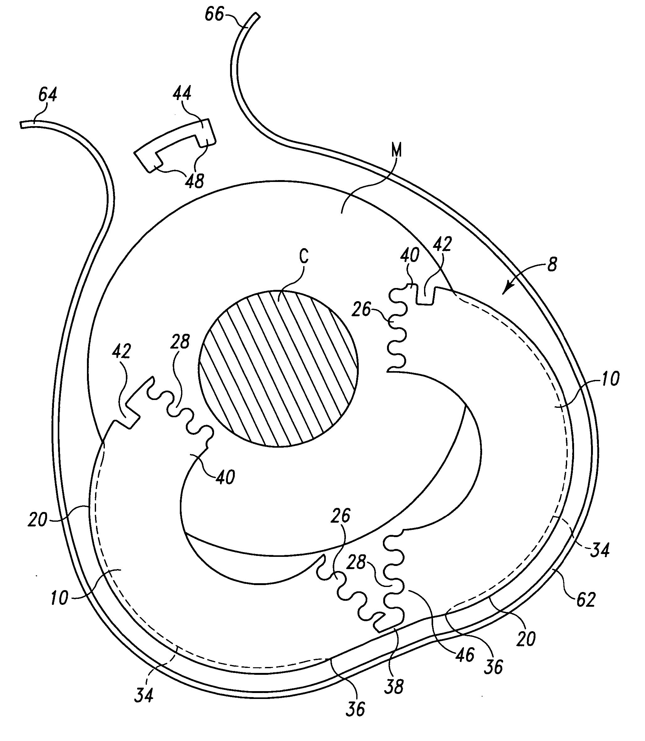
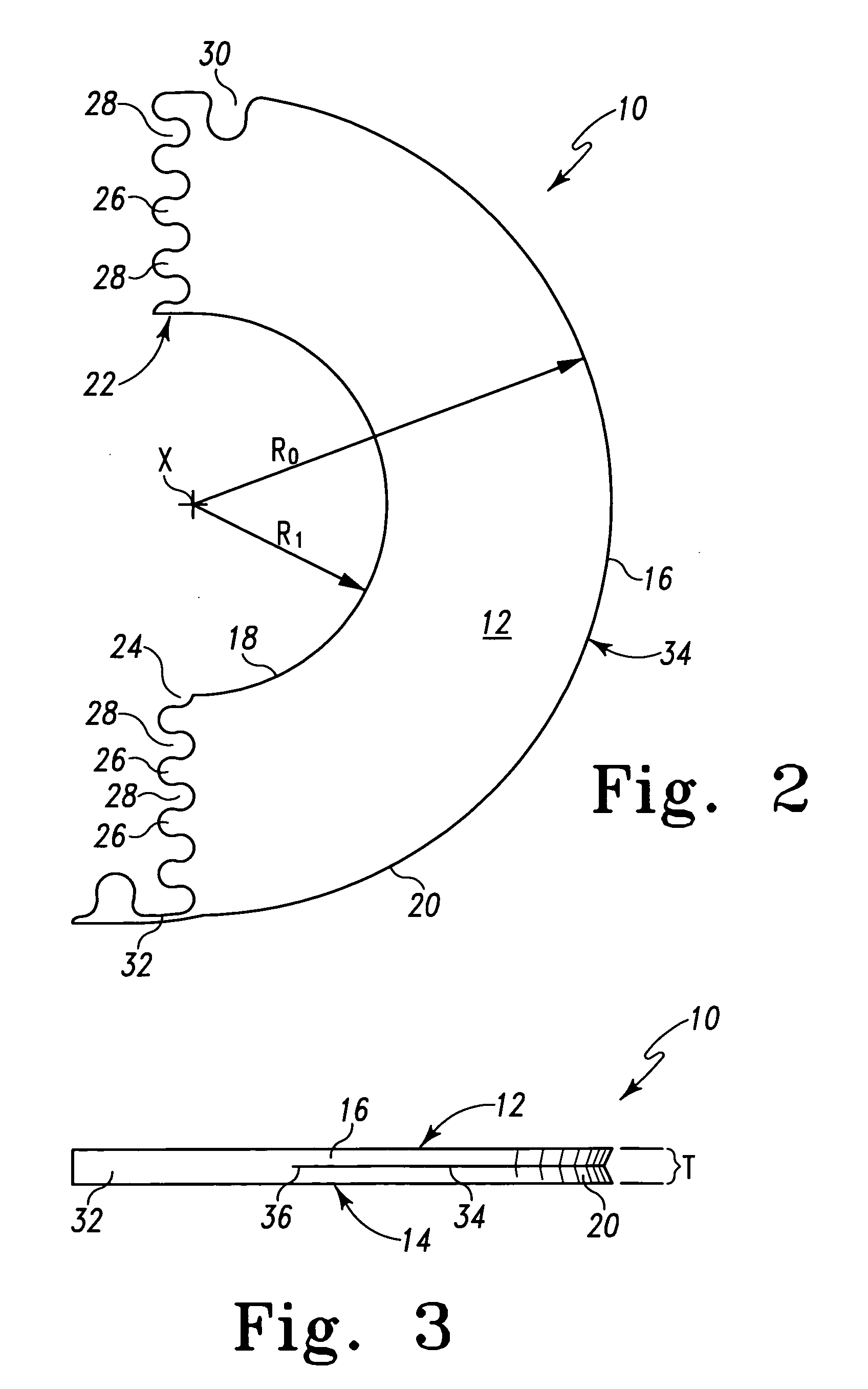
[0025] A C-shaped section 10 for forming a washer 8 of the present invention is shown in FIGS. 2 and 3. The section 10 has an upper surface 12 and a lower surface 14 that are parallel to each other and define the thickness T of the section 10. The thickness T can be selected to have any desired value necessary to match the opening in space S. Typically, the C-shaped sections 10 can be manufactur...


PUM


Abstract

A washer formed by two identical C-shaped sections having parallel upper and lower surfaces, two ends, an inside and an outside arcuate edge, the ends having a plurality of tabs and recesses that inter-digitate to form continuous surfaces. The outside arcuate edges have a circumferentially extending groove adapted to receive a circumferentially disposed tension member to apply a substantially uniform radial compression on the washer slot during assembly. The tension member can be molded into the groove to form a single unitary structure with the remainder of the washer.

Description

CROSS-REFERENCE TO RELATED APPLICATION [0001] This application is a continuation-in-part of our co-pending application Ser. No. 10 / 419,351 filed Apr. 21, 2003.BACKGROUND [0002] The present application is directed to washers used in mechanical structures, and particularly to washers that can be inserted in an existing mechanical structure without disassembly of that structure. [0003] Often mechanical structures and equipment that include coupled elements, which are designed for some relative movement and have been used for some time, develop an undesirable wobble or play between the coupled elements. This wobble or play can often be reduced to an acceptable level or even eliminated by the insertion of a washer of suitable thickness between the two coupled elements. It is most desirable if the washer can be inserted without disassembling the mechanical structure. [0004] One such washer disclosed in U.S. Pat. No. 1,558,364 is formed of two semi-cylindrical sections of identical constru...

Claims


Application Information

Patent Timeline
IPC IPC(8): F16B43/02F16B43/00
CPCF16B43/006F16B43/007
Inventor UNDERWOOD, J. LARRYTUMLIN, RICKY W.
Owner UNDERWOOD J LARRY
Why Eureka
Try Eureka