Supercharge Your Innovation With Domain-Expert AI Agents!

Taking air away from the tips of the rotor wheels of a high pressure compressor in a turbojet

a turbojet and compressor technology, applied in the field of turbojets, can solve the problems of degradingaffecting the performance of the turbojet, and affecting the achieving the effects of improving the drive efficiency of the turbojet, and reducing the cost of the compressor

Active Publication Date: 2006-08-17
SN DETUDE & DE CONSTR DE MOTEURS DAVIATION S N E C M A
View PDF5 Cites 9 Cited by
  • Summary
  • Abstract
  • Description
  • Claims
  • Application Information

AI Technical Summary

Benefits of technology

The present invention provides a turbomachine compressor with improved efficiency and operating safety margin compared to prior art devices. This is achieved by a design that includes a plurality of stationary vanes and a stationary casing with bleed holes. The bleed holes are located at a specific angle and diameter to the blade chord length, and are designed to take air away from the tips of the moving blades. This increases the pumping margin and improves efficiency. The ratio between the air flow rate through the turbomachine and the bled-off air flow rate is preferably between 0.1% and 5%. The stationary casing may also include oblique tongues oriented at the same angle as the moving blades. The bleed holes have a first axis of inclination in the range of 30° to 90° and a second axis of inclination perpendicular to the first in the range of 30° to 90°. The bleed holes may be staggered or formed by axially symmetrical slots and may also be non-circular.

Problems solved by technology

In the high pressure axial compressors of turbojets for turboprops (referred to below as “turbomachines”), it is known that the clearance that exists between the tips of the moving blades of the compressor and the casing forming the inside wall of the air flow channel degrades the drive efficiency of the turbomachine.
That arrangement is nevertheless relatively complex and difficult to implement.

Method used


Image

  • Taking air away from the tips of the rotor wheels of a high pressure compressor in a turbojet
  • Taking air away from the tips of the rotor wheels of a high pressure compressor in a turbojet
  • Taking air away from the tips of the rotor wheels of a high pressure compressor in a turbojet

Examples


Embodiment Construction

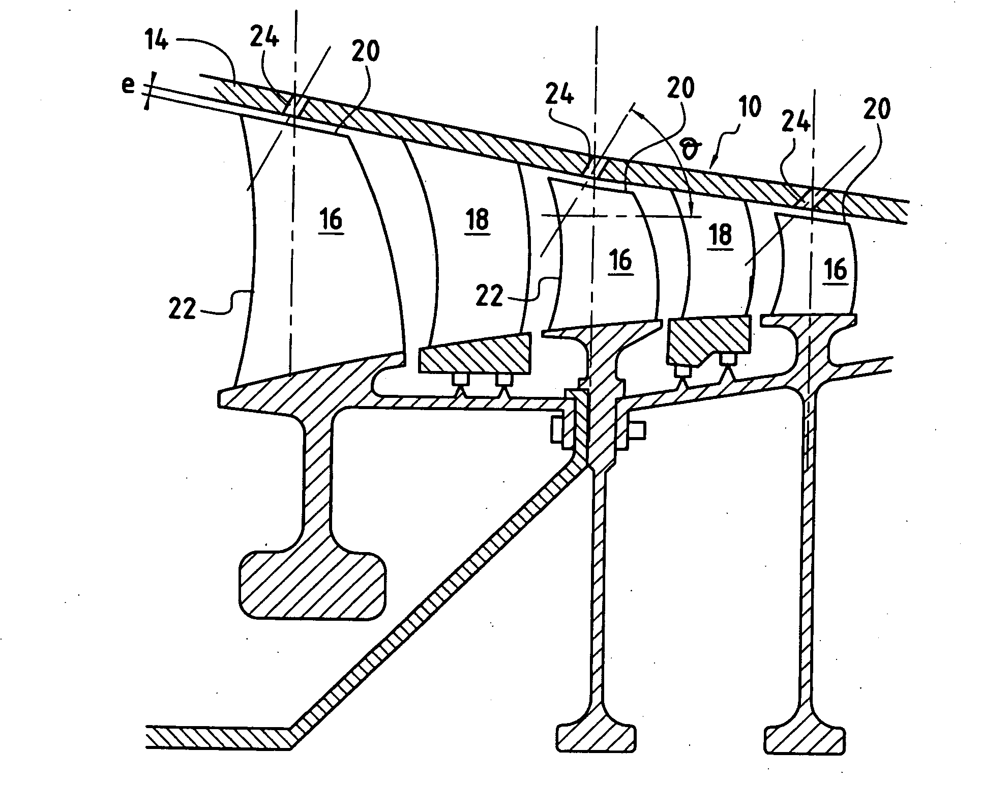
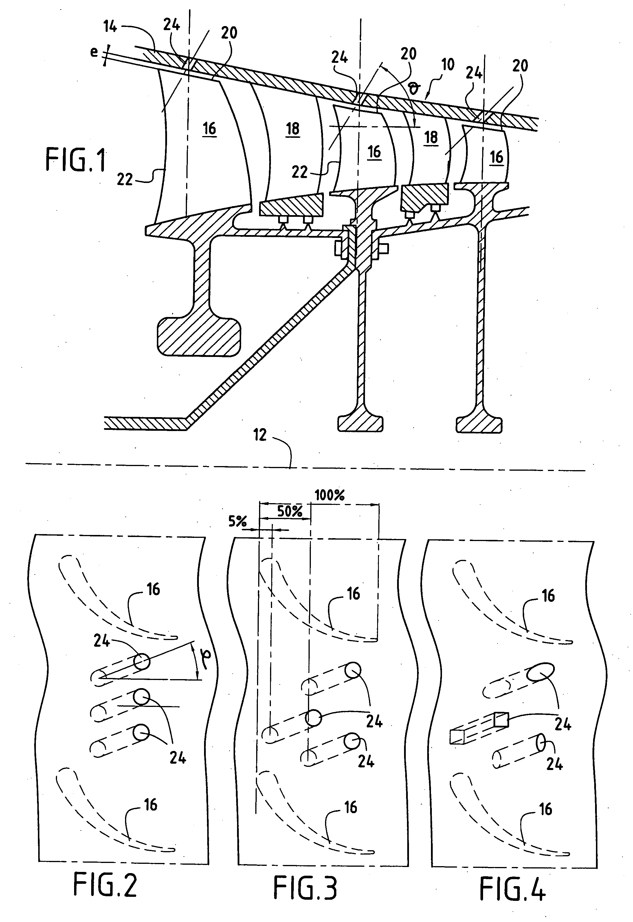
[0020]FIG. 1 is a diagrammatic view of a section of a high pressure axial compressor 10 disposed around a longitudinal central axis (drive axis 12) of a turbomachine, and defined on its outside by a casing 14 forming a surface of revolution around the central longitudinal axis. The compressor comprises a plurality of compression stages in succession (in an axial direction), each stage comprising, distributed around an entire circumference, a plurality of moving or “rotor” blades 16 capable of turning about the drive axis, and a plurality of stationary or “stator” vanes 18. Clearance e exists between the outer tip 20 of each moving blade and the stationary casing 14 that surrounds the compressor. This clearance can be the site of violent turbulence that can deteriorate the flow configuration between these various stages and can thus lead to degraded performance of the compressor, or in the extreme can lead to a phenomenon that is known as “pumping” or “separation” constituted by an i...


PUM


Abstract

A turbomachine compressor comprises at least one plurality of moving blades and spaced apart therefrom in an axial direction relative to a central longitudinal axis of the turbomachine, a plurality of stationary vanes, and a stationary casing surrounding said plurality of moving blades and including a plurality of bleed holes centered in the range 5% to 50% of the blade chord length and having a diameter less than or equal to 30% of the blade chord length, each bleed hole sloping at two angles of inclination relative to the central longitudinal axis. Advantageously, each bleed hole has a first axis of inclination presenting an angle φ relative to the central longitudinal axis lying in the range 30° to 90°, and a second axis of inclination perpendicular to the first and presenting an angle θ relative to the central longitudinal axis lying in the range 30° to 90°.

Description

FIELD OF THE INVENTION [0001] The present invention relates to the specific field of turbomachines, and it relates more particularly to a device for bleeding air from the air flow channel in a high pressure axial compressor of such a turbomachine. PRIOR ART [0002] In the high pressure axial compressors of turbojets for turboprops (referred to below as “turbomachines”), it is known that the clearance that exists between the tips of the moving blades of the compressor and the casing forming the inside wall of the air flow channel degrades the drive efficiency of the turbomachine. In addition, this clearance can significantly modify and degrade the operation of the compressor to the extent of a so-called “pumping” phenomenon appearing. One solution to that problem is given in French patent No. 2 564 533 which, in order to avoid pumping in an axial compressor, describes a specific way of shaping the casing in association with a specific arrangement of an air flow system. That arrangemen...

Claims


Application Information

Patent Timeline
Patent Type & Authority Applications(United States)
IPC IPC(8): F04D29/08
CPCY10S415/914F04D29/682F04D27/0207F04D29/685F04D29/526F04D27/023
Inventor TOUYERAS, ARMEL
Owner SN DETUDE & DE CONSTR DE MOTEURS DAVIATION S N E C M A
Features
  • R&D
  • Intellectual Property
  • Life Sciences
  • Materials
  • Tech Scout
  • Unparalleled Data Quality
  • Higher Quality Content
  • 60% Fewer Hallucinations
Learn More