Unitary pivoting spreader apparatus

a spreader and pivoting technology, applied in the field of spreader equipment, can solve the problems of difficult to achieve uniform coverage, sideward adjustment, and known apparatus relying on relatively complex adjustment mechanisms, and achieve the effect of avoiding or overcoming one or more shortcomings

Active Publication Date: 2006-08-17
BLUE LEAF I P INC
View PDF18 Cites 36 Cited by
  • Summary
  • Abstract
  • Description
  • Claims
  • Application Information

AI Technical Summary

Benefits of technology

[0007] What is disclosed is spreader apparatus for a crop residue chopper of an agricultural harvesting machine or combine, which spreader apparatus is quickly and precisely pivotable in a unitary manner for varying a direction of discharge of crop residue propelled from a chopper, for such purposes as aligning a pattern of crop residue deposition on a field responsive to, or, in anticipation of, conditions such changes in wind direction and / or velocity, and / or changes in direction of movement and the like, which is simpler than known constructions, and avoids or overcomes one or more shortcomings and problems of the prior art devices. In terms of pivotability, the spreader is sidewardly pivotable, and can optionally be pivotable upwardly and downwardly, both in a unitary manner to allow a wide range of options for adjustment.

Problems solved by technology

Further, the accuracy of the placement of the crop residue in relation to a harvested swath is important, as it is generally not desirable to distribute the crop residue in a manner so as to leave uncovered strips or areas of the swath, double covered areas, or to spread the residue in an adjacent area of unharvested crops so as to be possibly inducted into and processed by the machine.
It has been found, however, that such uniform coverage can be difficult to achieve when conditions vary, which conditions can include winds, particularly cross winds; the contours of a field or obstacles therein require following curved swaths; and when turning is required, such as in the headlands of a field.
An observed disadvantage of such known spreader apparatus is that sideward adjustment of the locations of the edges of a pattern of crop residue deposited on a field, for instance, for aligning with edges of a swath of harvested crops, is made by adjusting the sideward extent or width of the pattern.
In this latter regard, the known apparatus rely on relatively complex adjustment mechanisms for the guiding plates or vanes, in addition to other mechanisms or apparatus for supporting the spreader itself, such as hinges, locking devices, and the like, for upward and downward movement.
Some of such mechanisms have been found to have less than desirable durability and require more frequent than desirable adjustment.
Operationally, other possible shortcomings of using such complex linkage arrangements include that end play and manufacturing tolerances may make precise adjustments more difficult and time consuming.
And, altering the sideward position or orientation of vanes may undesirably change one or more characteristics of the pattern of residue deposition, such as the uniformity or consistence of coverage, or the like.

Method used


Image

  • Unitary pivoting spreader apparatus
  • Unitary pivoting spreader apparatus
  • Unitary pivoting spreader apparatus

Examples


Embodiment Construction

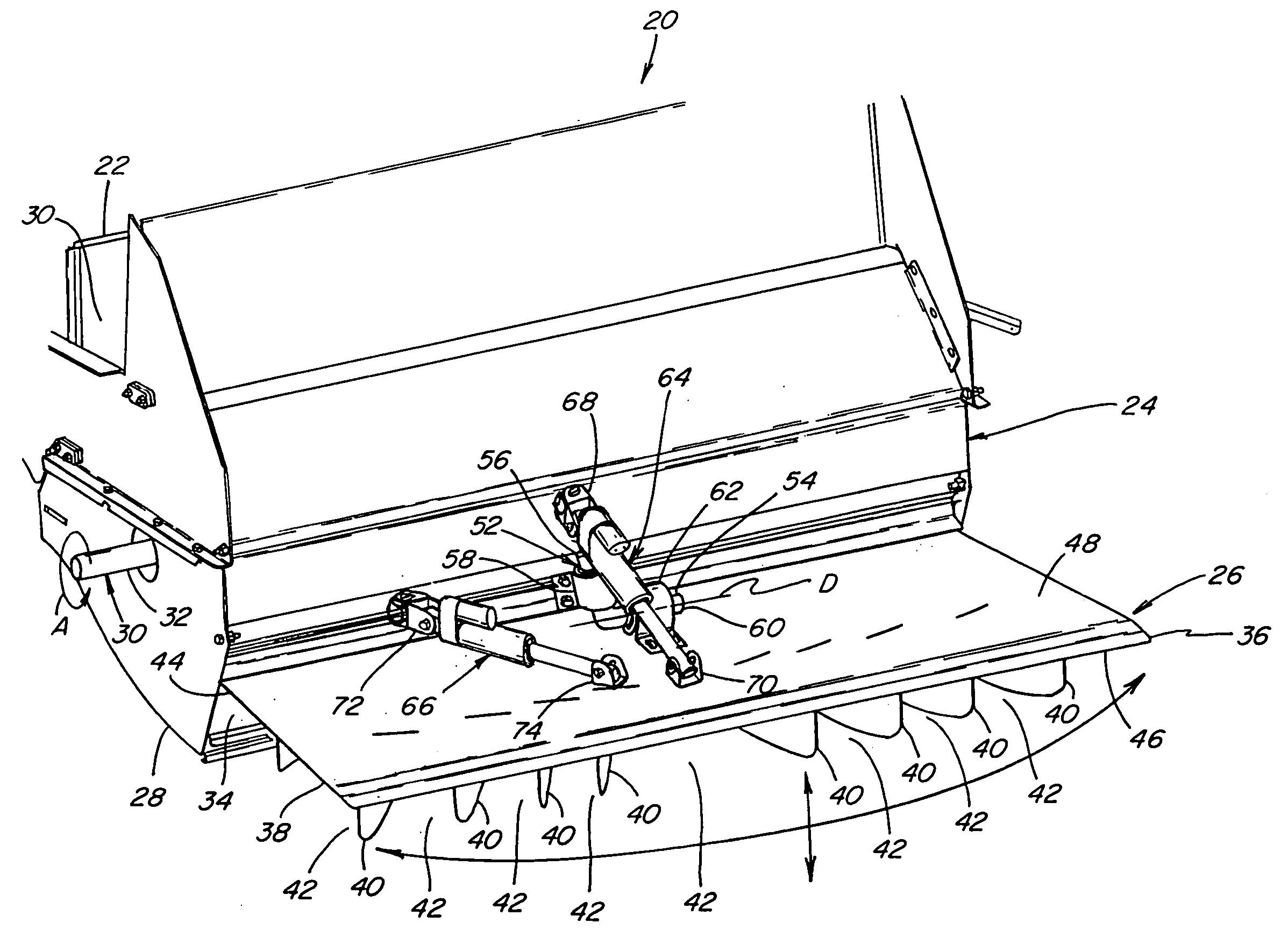
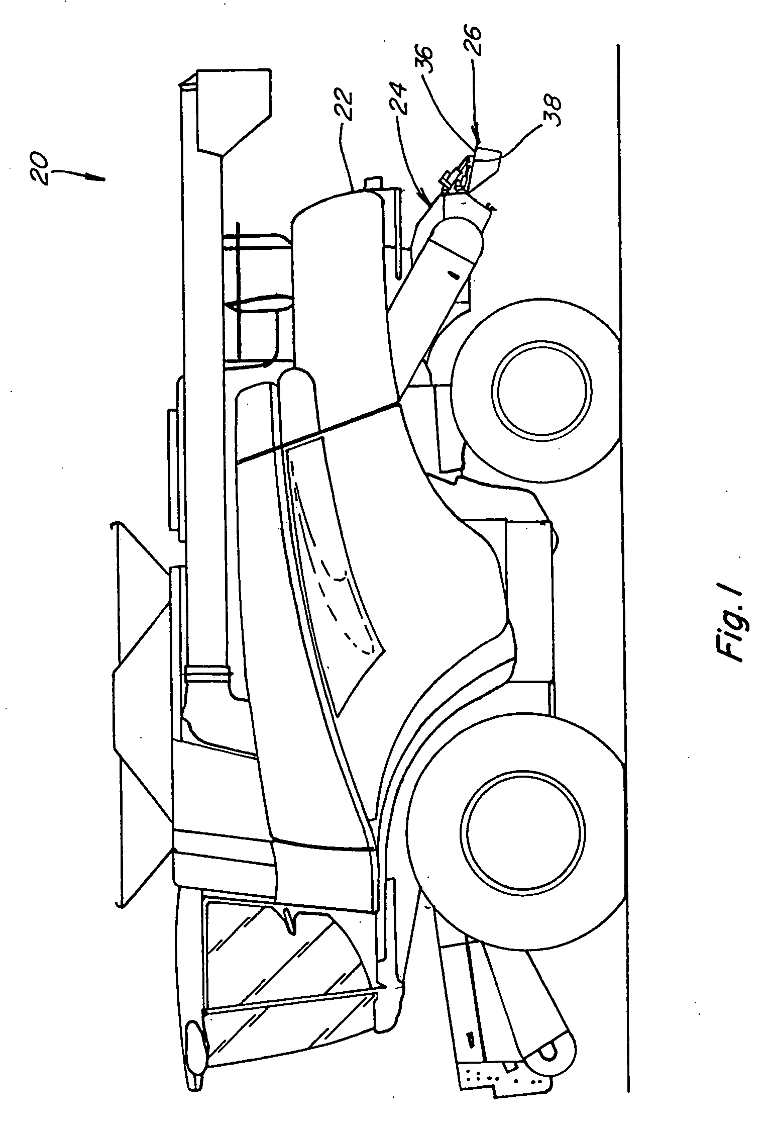
[0024] Referring now to the drawings, wherein preferred embodiments of the present invention are shown, in FIG. 1 a self-propelled agricultural combine 20 is shown, including a rear end 22 having a crop residue chopper 24 mounted thereon in the conventional manner, and operable for propelling a flow of crop residue therefrom, for deposition in a desired pattern over a field by a spreader 26 constructed and operable according to the teachings of the present invention.

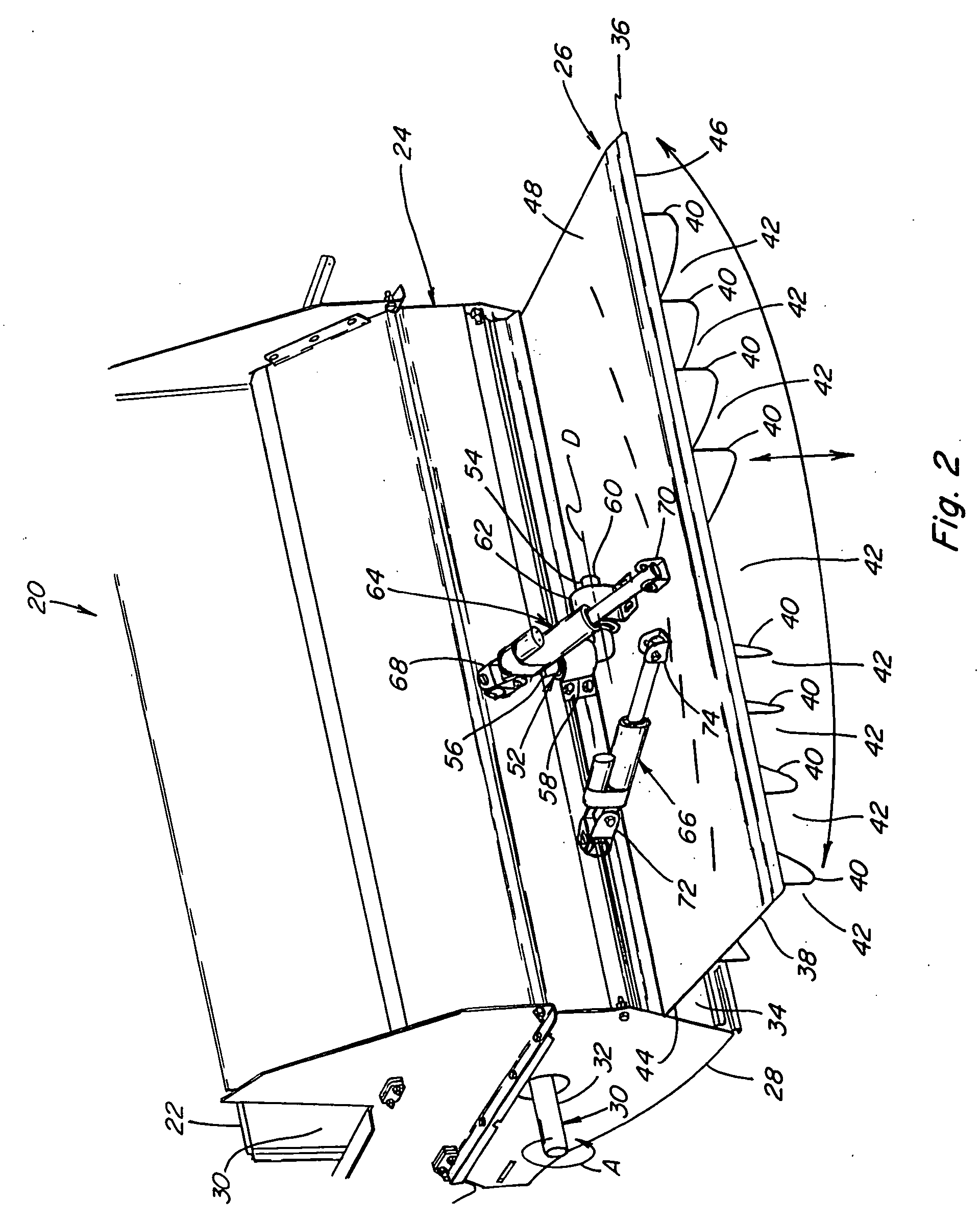
[0025] Referring also to FIG. 2, chopper 24 includes a housing 28 which receives a flow of crop residue through a forward opening 30, from a threshing system (not shown) of combine 20. Housing 28 contains a rotary device 30 powered by combine 20 and including a rotatably driven shaft 32, which carries a plurality of knives or flails (also not shown) for rotation in the direction indicated by arrow A, for propelling the crop residue through housing 28 and outwardly therefrom through a discharge outlet 34. Housing 28 cont...


PUM


Abstract

Spreader apparatus for a crop residue chopper of an agricultural harvesting machine or combine, mountable in a simple manner and quickly and precisely pivotable sidewardly, and optionally upwardly and downwardly, in a unitary manner, for adjusting or varying a direction and/or one or more characteristics of discharge of crop residue propelled from a chopper. The spreader apparatus includes a spreader board having vanes mounted thereon for guiding crop residue flow discharged from the chopper, the vanes and the spreader board being movable simultaneously and in a unitary manner, to achieve adjustments or shifts in crop residue deposition location, without altering consistency or uniformity of the crop residue distribution.

Description

TECHNICAL FIELD [0001] This invention relates generally to spreader apparatus for a crop residue chopper of an agricultural harvesting machine or combine, and more particularly, to spreader apparatus which is mountable in a simple manner and quickly and precisely pivotable sidewardly, and optionally upwardly and downwardly, in a unitary manner, for adjusting or varying a direction and / or one or more other characteristics of a flow of crop residue propelled from a chopper. BACKGROUND ART [0002] Currently, agricultural harvesting machines such as combines typically include a chopper which can be used for chopping and / or propelling crop residue onto a harvested field, which will typically include stalks, leaves and cobs separated from corn or maize; straw and chaff separated from wheat and other grasses; and stalks, leaves and pods of legumes such as soybeans. In many instances it is desirable for the crop residue to be spread as evenly as possible over the width of the harvested swath...

Claims


Application Information

Patent Timeline
Patent Type & Authority Applications(United States)
IPC IPC(8): A01F12/30
CPCA01D41/1243
Inventor BENES, JASON M.
Owner BLUE LEAF I P INC
Why Eureka
Try Eureka