Spreader roll

a roller and roller body technology, applied in the direction of shafts, portable power tools, stretching, etc., can solve the problems of non-uniform curvature and comparatively expensive known solutions, and achieve the effect of infinite fine adjustment and simple solution

Inactive Publication Date: 2006-08-17
STOWE WOODWARD
View PDF32 Cites 12 Cited by
  • Summary
  • Abstract
  • Description
  • Claims
  • Application Information

AI Technical Summary

Benefits of technology

[0006] The shaping of the central area as a deformable axis is a particularly simple solution. It allows as necessary the mounting of the bearings along the entire length of the axis with infinite fine separation adjustment. So that the bearings rest against the inner wall of the roller sleeve with only slight surfac...

Problems solved by technology

The known solution is comparatively expensive.
Such a mounti...

Method used


Image

  • Spreader roll
  • Spreader roll
  • Spreader roll

Examples


Embodiment Construction

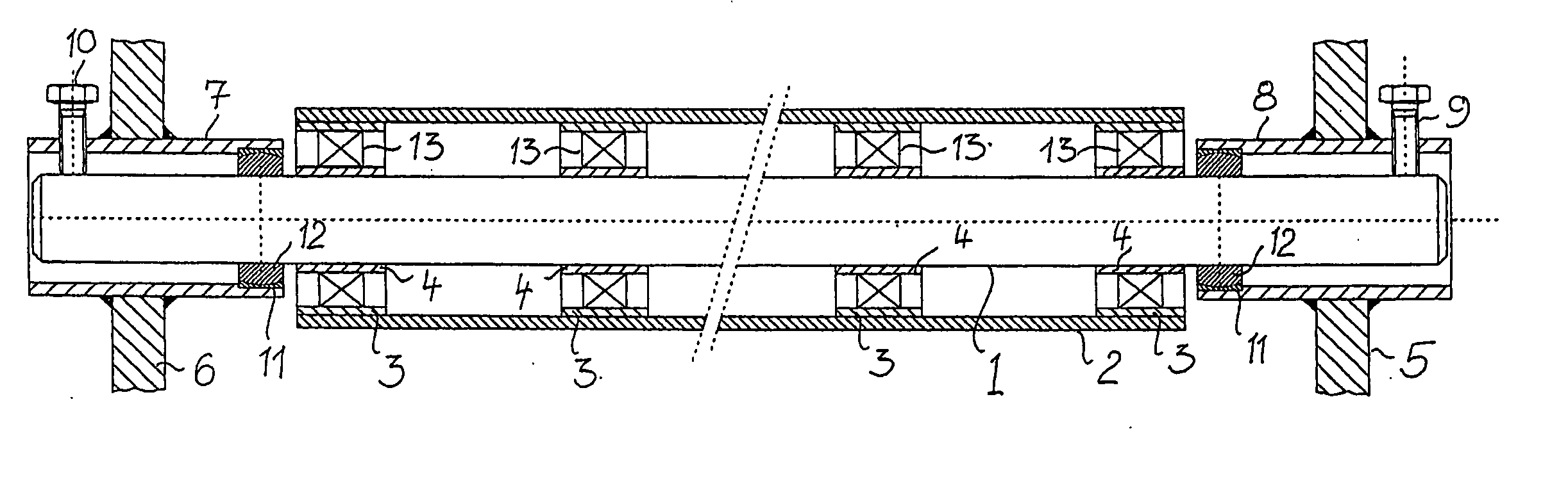
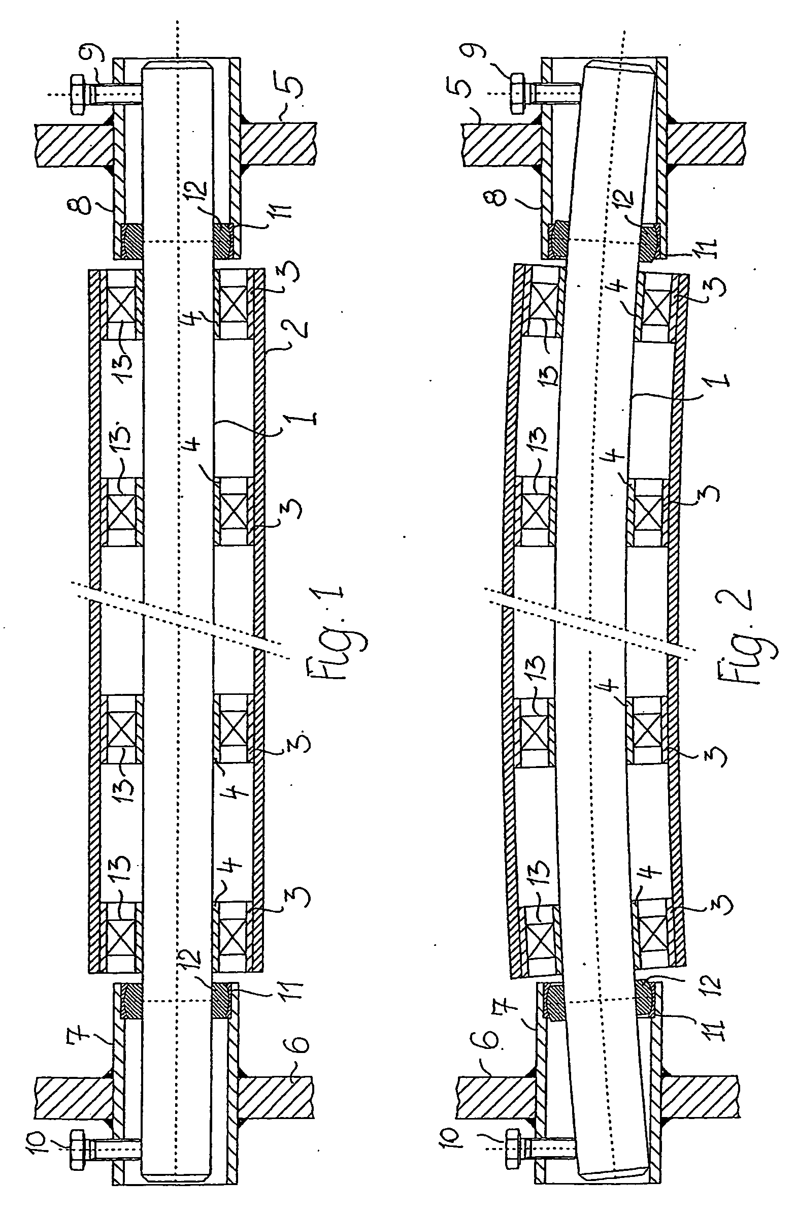
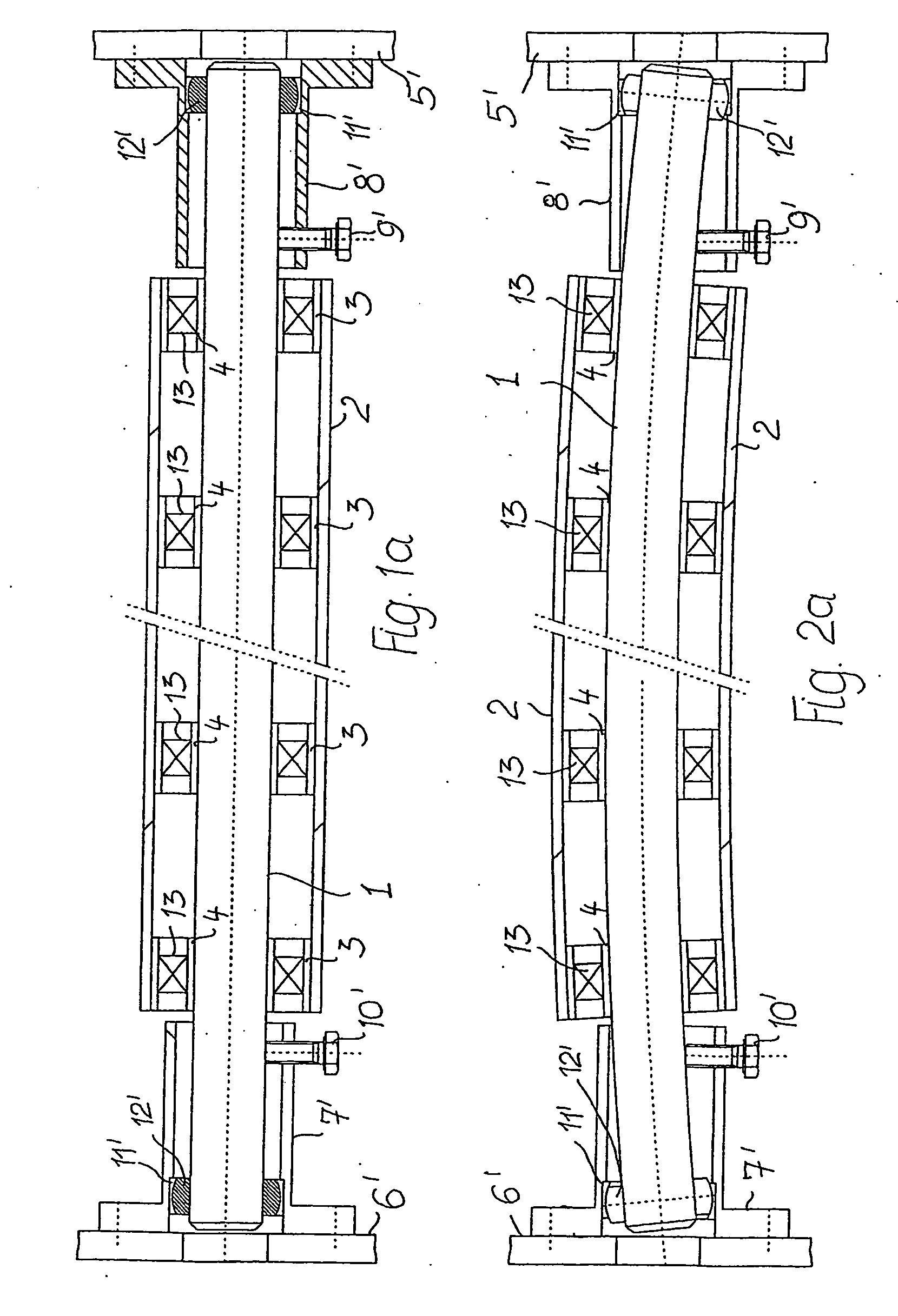
[0014] In the various Figures, identical or analogous parts are identified using uniform indexes. They are differentiated from one another merely by the use of apostrophes.

[0015] A roller sleeve 2 is mounted on a deformable axis 1 by means of bearings 13. Outer ring shell bushings 3 are positioned between the inner wall of the roller sleeve 2 and the outer surfaces of the bearings 13. Inner ring shell bushings 4 are positioned between the inner surfaces of the bearings 13 and the deformable axis 1. The roller sleeve 2 consists of a plastic / composite material reinforced with glass or carbon fibers (fiberglass or carbon composite). The widths of the inner ring shell bushings 4 and the outer ring shell bushings 3 are greater than the width of the pertinent bearing 13. The bearings are usually roller bearings, e.g., ball bearings.

[0016] The ends of the deformable axis 1 are mounted on facing frame areas 5 and 6 of a machine frame. Bushings 7 and 8 are provided in the frame areas 5 and...


PUM

PropertyMeasurementUnit
Lengthaaaaaaaaaa
Areaaaaaaaaaaa

Abstract

An expander roller includes a tubular roller sleeve 2 adjustable in its curvature that is formed of one-piece tubes made of reinforced plastic/composite material, and that is mounted on a non-rotatable central area by means of bearings 13. The central area is a deformable axis. The outer surfaces of the bearings 13 rest against the inner wall of the roller sleeve 2 or of one of the outer ring shell bushings 3 resting against its inner wall. The inner surfaces of the bearings 13 rest on the upper surface of the deformable axis 1 or of a ring shell bushing 4 firmly surrounding it.

Description

TECHNICAL FIELD [0001] The invention relates to an expander roller with a tubular roller sleeve adjustable in its curvature that is formed of one-piece tubes made of reinforced plastic / composite material, and that is mounted on a non-rotatable central area by means of bearings. BACKGROUND INFORMATION [0002] In an expander roller of the type disclosed in EP 0 932 723 B1, the non-rotatable central area is formed of two relatively short inner tube pieces on its face, onto which the bearings are mounted from within. The tubular pieces may be pivoted, and a curvature of the roller sleeve may result from this pivoting. [0003] The known solution is comparatively expensive. Mounting the roller sleeve on the central area is merely achieved near the roller sleeve ends, while the central area is not supported. Such a mounting arrangement may lead to instability and non-uniform curvature. SUMMARY [0004] Based on this State of the Art, it is the task of this invention to form an expander roller ...

Claims


Application Information

Patent Timeline
IPC IPC(8): B29C43/46B29C55/00B65H27/00D06C3/06D21F1/40F16C13/00
CPCB29C43/46B29C55/00B65H27/00B65H2404/1341B65H2404/1371B65H2404/172D06C3/067D21F1/40F16C13/003F16C2340/00B65H23/025D21F1/00
Inventor NIEMEYER, FRIEDEL
Owner STOWE WOODWARD
Why Eureka
Try Eureka