Implantable generating system

a technology of electrical generation system and generating system, which is applied in the direction of dynamo-electric components, medical science, therapy, etc., can solve the problem that batteries/battery packs have a finite life span

Inactive Publication Date: 2006-08-17
BAKER III REX M +1
View PDF10 Cites 70 Cited by
  • Summary
  • Abstract
  • Description
  • Claims
  • Application Information

AI Technical Summary

Benefits of technology

[0005] One or more of the following features may also be included. An energy storage device (e.g., a battery or a capacitor) may be electrically coupled to the generator assembly to store the electrical energy. The generator assembly may include a rotor assembly and a stator a...

Problems solved by technology

Unfortunately, these batteries/battery packs have a fi...

Method used


Image

  • Implantable generating system
  • Implantable generating system
  • Implantable generating system

Examples


Embodiment Construction

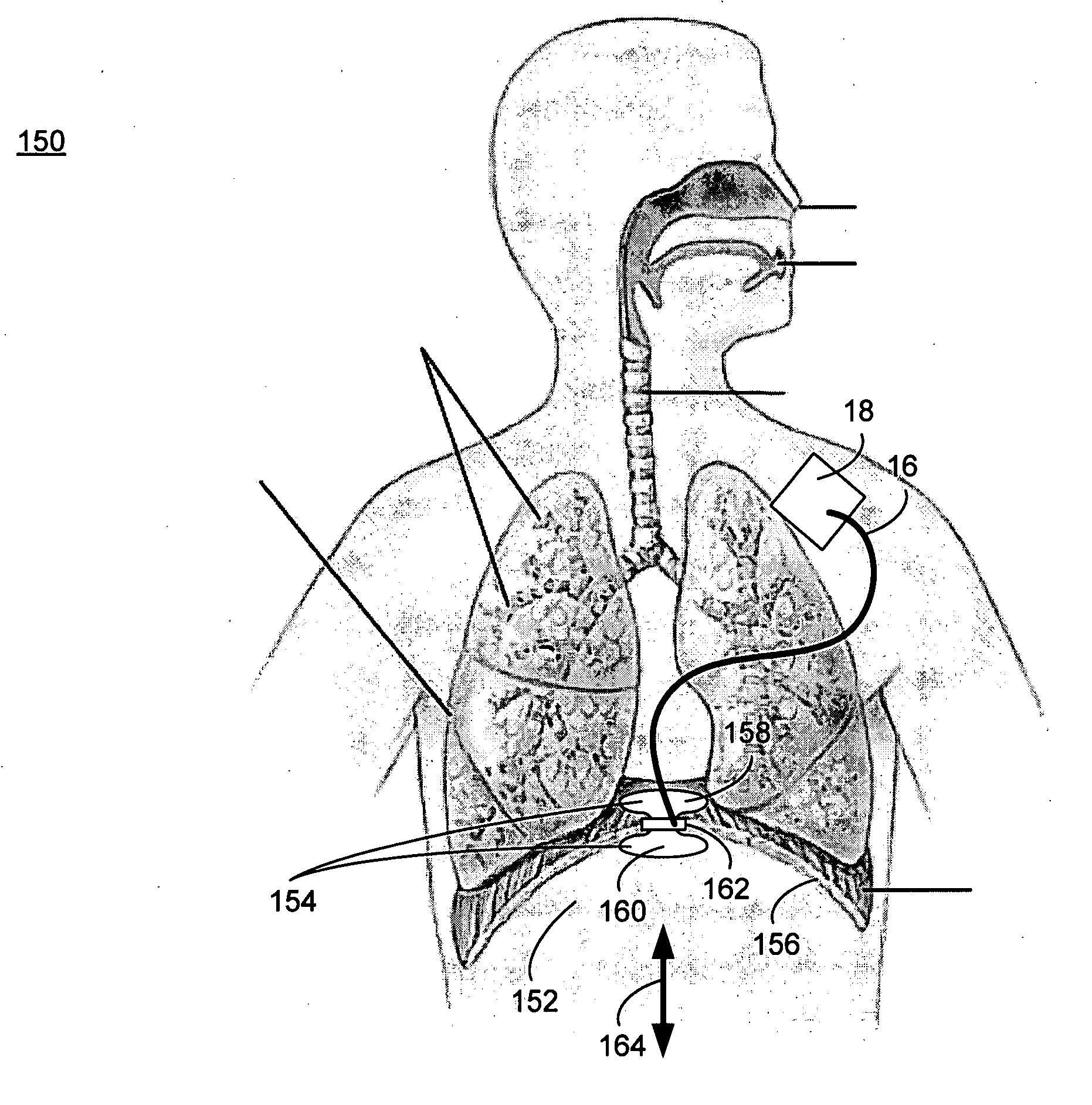
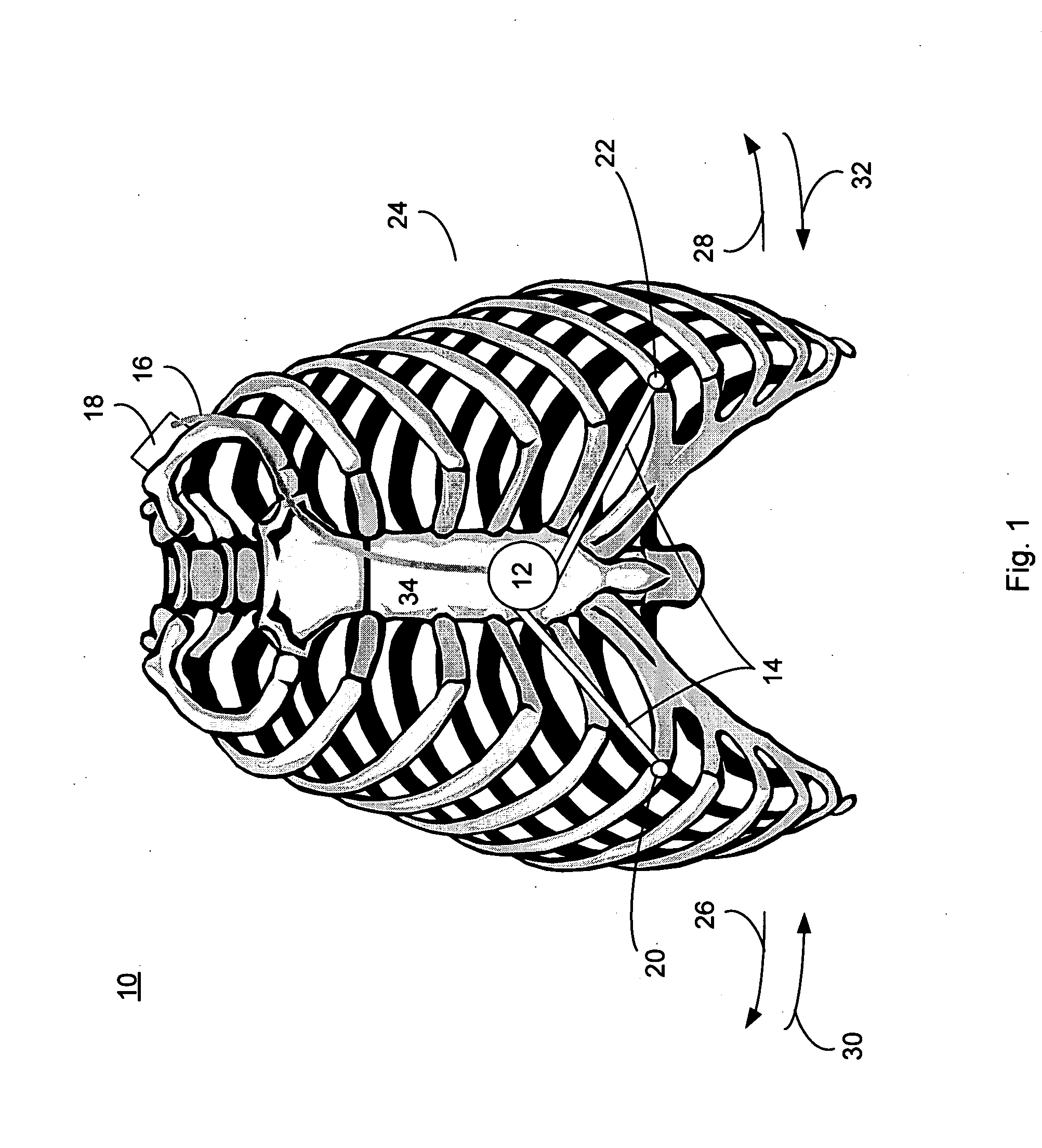
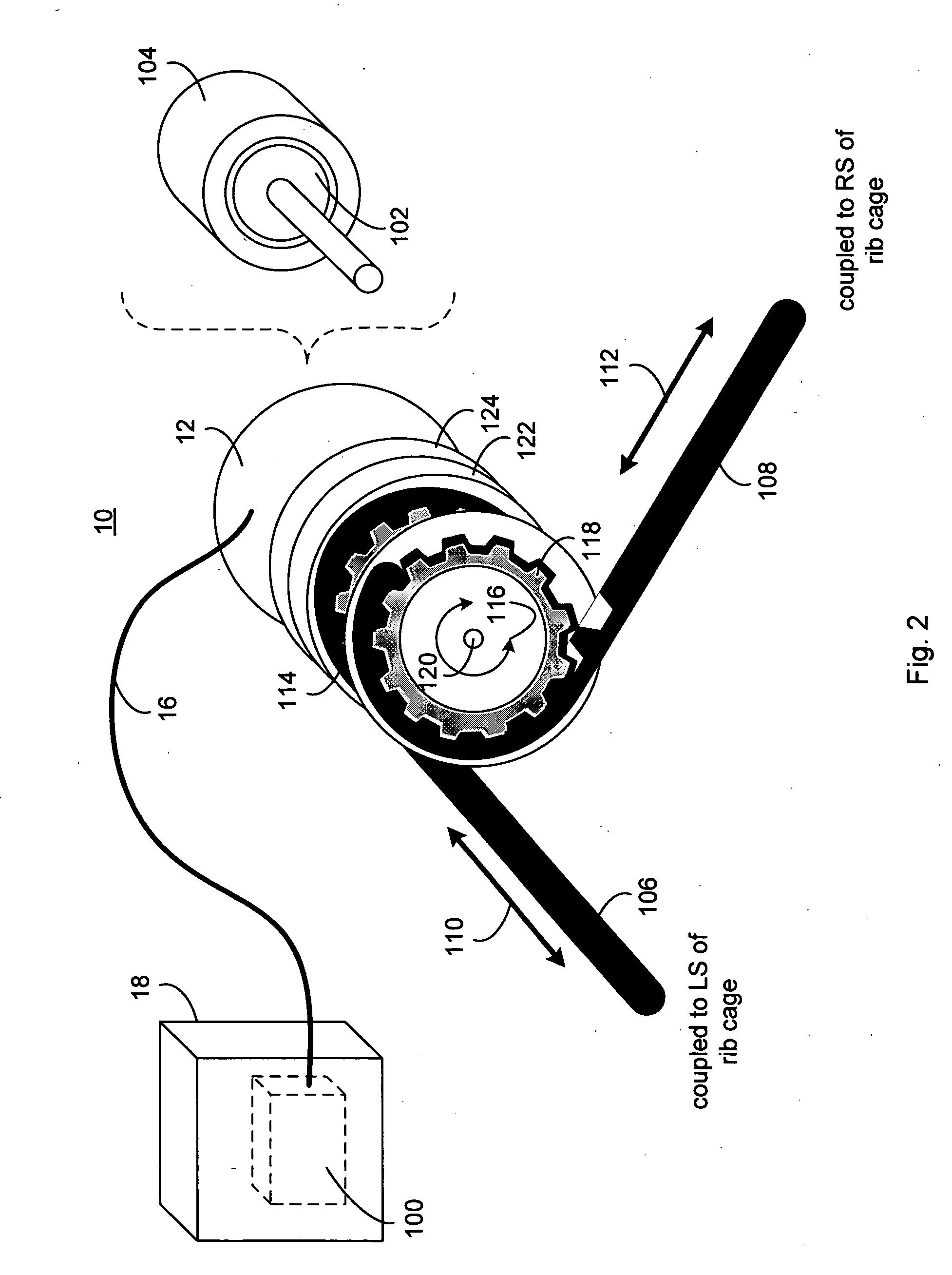
[0022] Referring to FIG. 1, there is shown an implantable generation system 10 that includes a generator assembly 12 and a linkage assembly 14. Implantable generation system 10 may be implanted into any breathing organism (e.g., a human being or an animal) and is typically constructed of an implantable material (e.g., surgical steel, platinum, ceramic, cobalt chromium alloy, and / or ferric magnets). Generator assembly 12 is typically an alternating current or direct current generator (to be discussed below in greater detail) that generates electrical energy that is supplied (via lead 16) to implanted medical device 18. Examples of medical device 18 include a pacemaker, a defibrillator, a bone growth stimulation device, a pain attenuation device, a brain implant device, a cochlear implant device, a sphincter muscle stimulation device, for example.

[0023] In this embodiment, linkage assembly 14 mechanically couples generator assembly 12 to two portions 20, 22 of the rib cage 24 that mo...


PUM


Abstract

An implantable generating system includes a generator assembly for converting mechanical motion into electrical energy. A linkage assembly, which is mechanically coupled to the generator assembly, converts respiratory motion into mechanical motion.

Description

FIELD OF THE DISCLOSURE [0001] This disclosure relates to electrical generation systems and, more particularly, to implantable electrical generation systems. BACKGROUND [0002] Medical devices are often implanted into humans and animals as a means for achieving a desired result. Examples of these implanted medical devices include: pacemakers (i.e., a device used to stimulate or regulate contractions of the heart muscle); defibrillators (i.e., a device used to counteract fibrillation of the heart muscle and restore a normal heartbeat by applying a brief electric shock); bone growth stimulation devices, pain blocking / attenuation devices, brain implant devices, and cochlear implant devices, for example. Typically, these devices are powered by an internal battery or external battery pack (i.e., a battery pack implanted within the patient but external to the medical device). [0003] Unfortunately, these batteries / battery packs have a finite life span and, after a period of time, must be re...

Claims


Application Information

Patent Timeline
IPC IPC(8): A61N1/378
CPCA61N1/3785H02K7/1876H02K35/02H02K7/1853H02K35/06
Inventor BAKER, REX M. IIIBAKER, JAMES R.
Owner BAKER III REX M
Why Eureka
Try Eureka