
Modular multi-articulated patient support system

a patient support system and multi-articulation technology, applied in the field of patient positioning and supporting systems, can solve the problems of obstructing the movement of c-arm mobile fluoroscopic imaging devices, bulky surgical tables with overhead frame structures, and use of dedicated operating rooms

Active Publication Date: 2006-08-24
WARSAW ORTHOPEDIC INC
View PDF19 Cites 50 Cited by
  • Summary
  • Abstract
  • Description
  • Claims
  • Application Information

AI Technical Summary

Benefits of technology

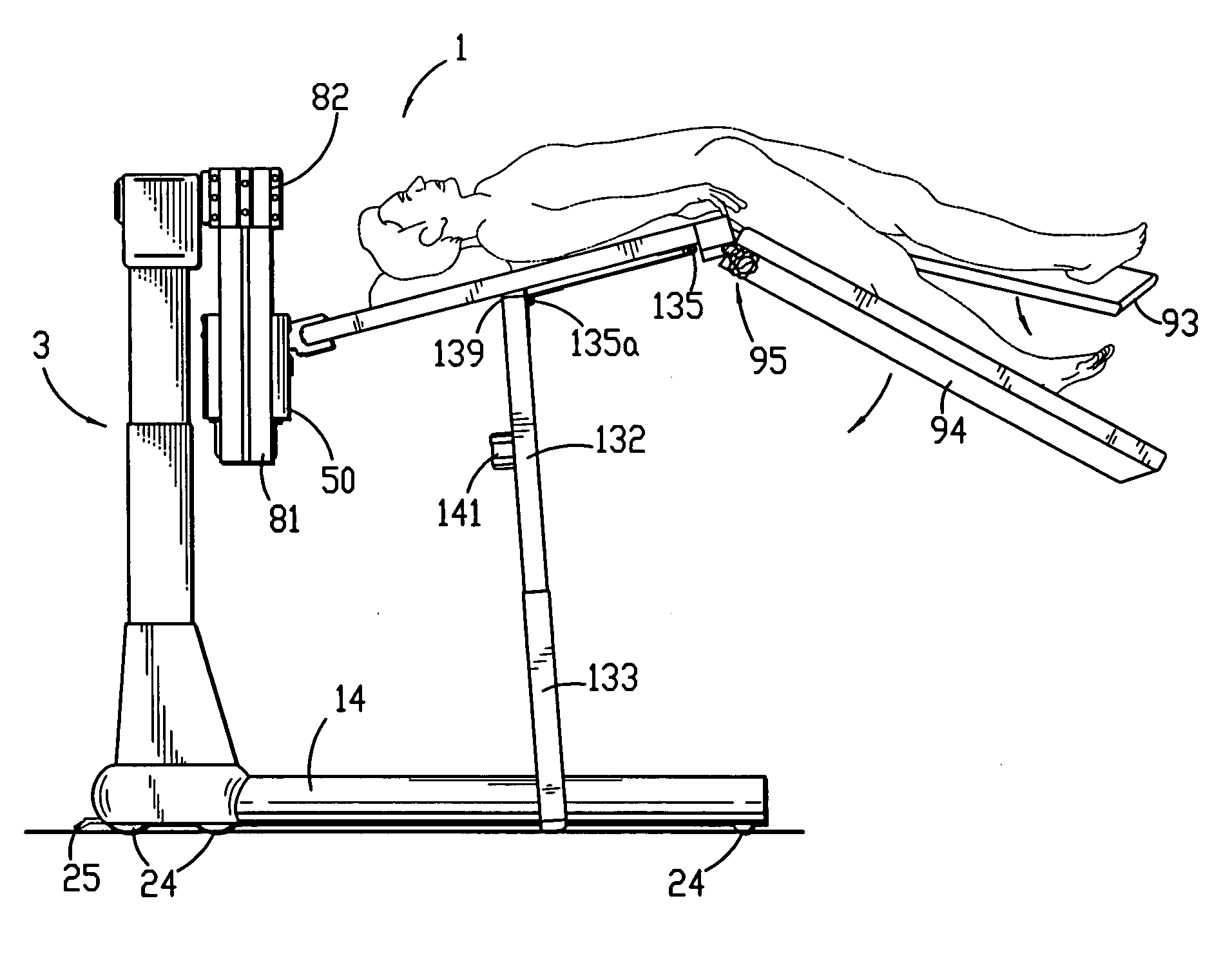
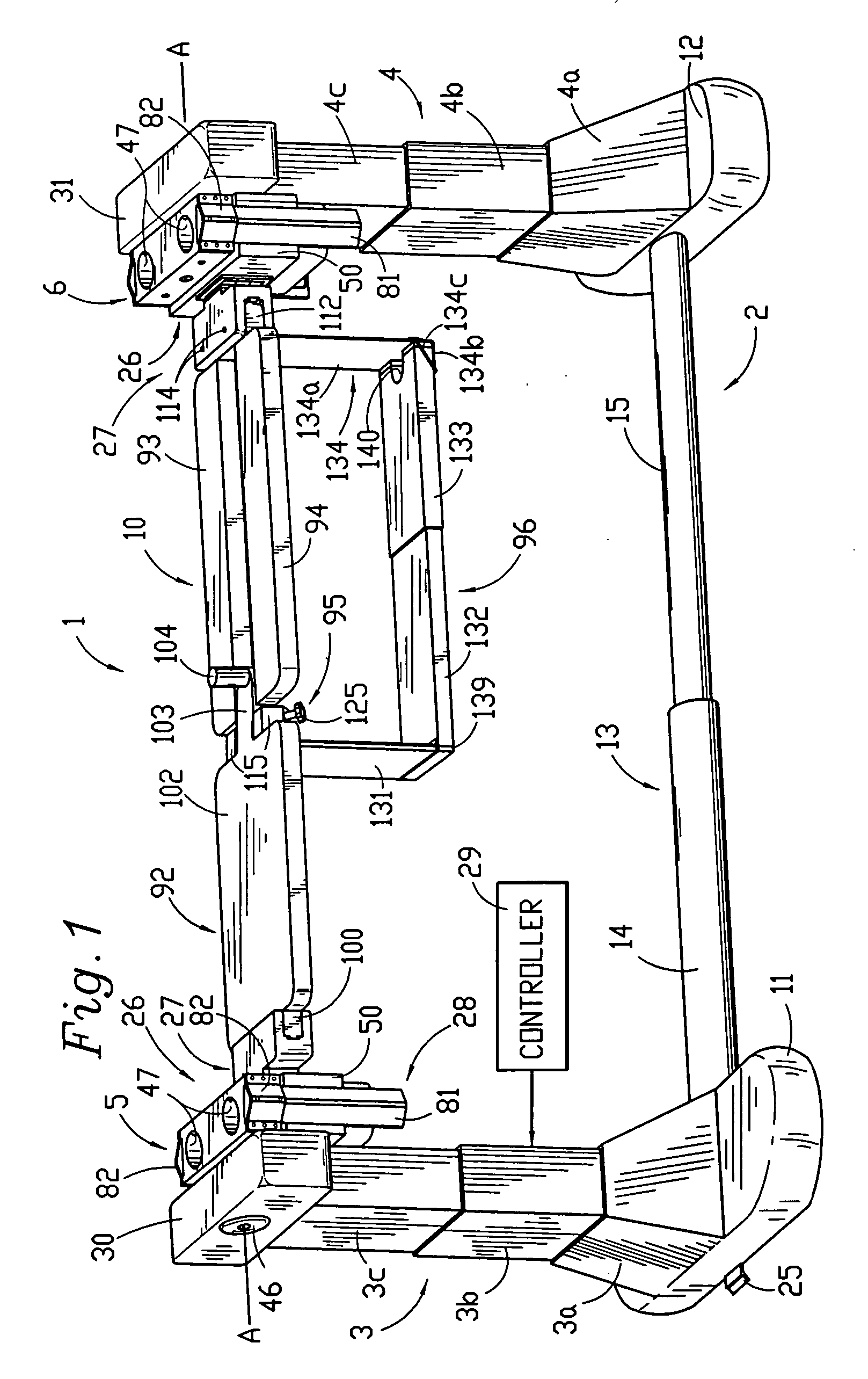
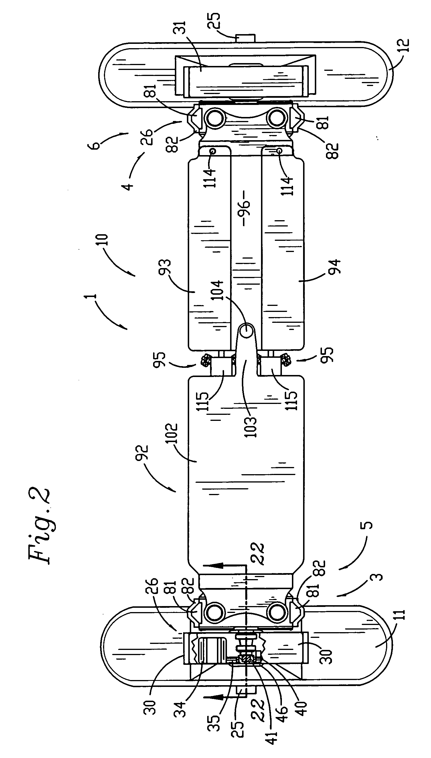
[0014] The patient support structure may also be configured to include two pairs of opposed patient supports which can be constructed as frames or boards that are attached in spaced relation at the outboard ends to a corresponding upright end support column. A coordinated drive system raises, lowers, tilts and rotates the supports, which may be positioned in overlapping relation when the base is adjusted to a shortened, retracted position. When in an aligned position, the pairs of patient supports may be rotated in unison about a longitudinal axis to achieve 180° repositioning of a patient, from a prone to a supine position.

Problems solved by technology

The enlarged base members associated with such cantilever designs are problematic in that they may obstruct the movement of C-arm mobile fluoroscopic imaging devices.
Surgical tables with overhead frame structures are bulky and may require the use of dedicated operating rooms, since in some cases they cannot be moved easily out of the way.
Neither of these designs is easily portable or storable.

Method used


Image

  • Modular multi-articulated patient support system
  • Modular multi-articulated patient support system
  • Modular multi-articulated patient support system

Examples


second embodiment

[0092] the patient support system of the invention is generally designated by the reference numeral 201 and is depicted in FIGS. 18-27 to include a base 202, support columns 203 and 204 and horizontal support assemblies 205 and 206 including rotation subassemblies 226, angulation subassemblies 227 and linear guide rail or separation subassemblies 228 substantially as previously described. The patient support structure 210 includes a pair of body boards 292 and 293, depicted as surgical tops and open frames (FIG. 18), although as previously discussed, other suitable structures such as slings, bolsters or a combination thereof may be employed. The boards 292 and 293 each include bracket engaging sections 300 that are received within channels 275 in brackets 283 attached to gear boxes 250. The inboard ends of the body boards 292 and 293 are free so that they may be independently raised and lowered by the support columns 203 and 204 (FIG. 26). The distance between the inboard ends may b...

third embodiment

[0101] the patient support system of the invention is generally designated by the reference numeral 401 and is depicted in FIGS. 28 to 33 to include a base, support columns 403 and horizontal support assemblies 405 including rotation subassemblies 426, angulation subassemblies 427 and separation subassemblies 428 substantially as previously described. The horizontal support assemblies 405 and 406 support a patient support structure 410 that includes patient head and foot boards or supports 492, 492a, 493, 493a (FIGS. 28, 32, 33), substantially as previously described with respect to FIGS. 18-27. The patient support structure 410 may also be configured as a single support, which may be articulated as previously described with respect to FIGS. 1-6.

[0102] The columns 403 include an elevation assembly 544 and the horizontal support assemblies 405 each further include a transverse or lateral shift subassembly 545, which subassemblies are interconnected by associated circuitry linked to a...


PUM


Abstract

A modular, multi-articulated patient support system includes independently adjustable columns connected by an adjustable base and supporting a patient support structure. Each column includes rotation, angulation, separation and lateral travel structure. The patient support may be raised, lowered and rotated about a transversely shiftable longitudinal axis in either horizontal or tilted orientation. The patient support includes a body support rotatably coupled with right and left leg supports disengageable at the outboard ends, that can be tilted, rotated and locked in place. An intermediate brace engages the base when the outboard ends of the leg supports are disengaged. The patient support structure may include two pairs of patient supports, each attached at the outboard end of a column and having a free inboard end. A coordinated drive system raises, lowers, tilts, rotates and laterally shifts the patient supports, which may be positioned in overlapping relation. The pairs of patient supports may be rotated in unison to achieve 180° repositioning of a patient.

Description

CROSS REFERENCE TO RELATED APPLICATION [0001] This application is a continuation-in-part of U.S. patent application Ser. No. 11 / 062,775 entitled MODULAR MULTI-ARTICULATED PATIENT SUPPORT SYSTEM filed Feb. 22, 2005.BACKGROUND OF THE INVENTION [0002] The present invention is broadly concerned with a system for positioning and supporting a patient during examination and treatment, including medical procedures such as imaging, surgery and the like. More particularly, it is concerned with a system having patient support modules that can be independently adjusted for selective positioning of portions of the patient's body by movement up and down, tilting, pivoting, angulating or bending of the trunk in a supine, prone or lateral position, multi-axial motion of joints, rotation of the patient about an axis from a prone to a lateral to a supine position, and that is suitable for integrated computer software actuation and in some applications for use in conjunction with robotics technology. ...

Claims


Application Information

Patent Timeline
IPC IPC(8): A61G13/08A61G13/00
CPCA61B6/0442A61G7/001A61G13/0036A61G13/04A61G13/08A61G2013/0054A61G2210/50A61G13/0054
Inventor JACKSON, ROGER P.
Owner WARSAW ORTHOPEDIC INC
Learn More