Straddle safety pusher system

a safety pusher and pusher technology, applied in the field of woodworking tools, can solve the problems of requiring the operator to touch the workpiece with a second unprotected hand, affecting the safety of the pusher,

Inactive Publication Date: 2006-08-24
WANG HENRY
View PDF40 Cites 20 Cited by
  • Summary
  • Abstract
  • Description
  • Claims
  • Application Information

AI Technical Summary

Problems solved by technology

While the push stick of the '521 patent does provide a degree of protection for the one hand of the operator, it still requires the operator to touch the work piece with a second unprotected hand.
Applying downward force only against the trailing edge portion of the work piece may be inadequate to hold the stock material down.
A long piece of stock material being urged into a saw blade with such a tool may be lifted away from the table by the lifting action of the rotating saw blade, thus creating a dangerous kick-back condition where the work piece is thrown upward toward the table saw operator.
U.S. Pat. No. 2,839,100 describes a woodworking accessory that engages the work piece along an extended length in order to keep the operator's hands away from the saw blade at all times. This device engages the stock material with a plurality of screws, thus causing undesirable damage to the work piece.
While this device provides improved control of the work piece between the saw blade and the fence guide face, it does not provide any control for the severed portion of the work piece on the far side of the blade away from the fence, commonly called the outside cut material.
While the outside cut material is often considered the scrap portion of the stock material, it nonetheless may present a danger to the operator if it is not properly restrained during the cutting operation.
Here, again, this tool engages the stock material only near its rear edge and is thus ineffective in restraining the leading edge portion of a long piece of stock material.
It includes no means for positively forcing the work piece against the guide fence, thus necessitating the use of the operator's second unprotected hand for maintaining pressure against the fence as the work piece is moved past the saw blade.

Method used


Image

  • Straddle safety pusher system
  • Straddle safety pusher system
  • Straddle safety pusher system

Examples


Embodiment Construction

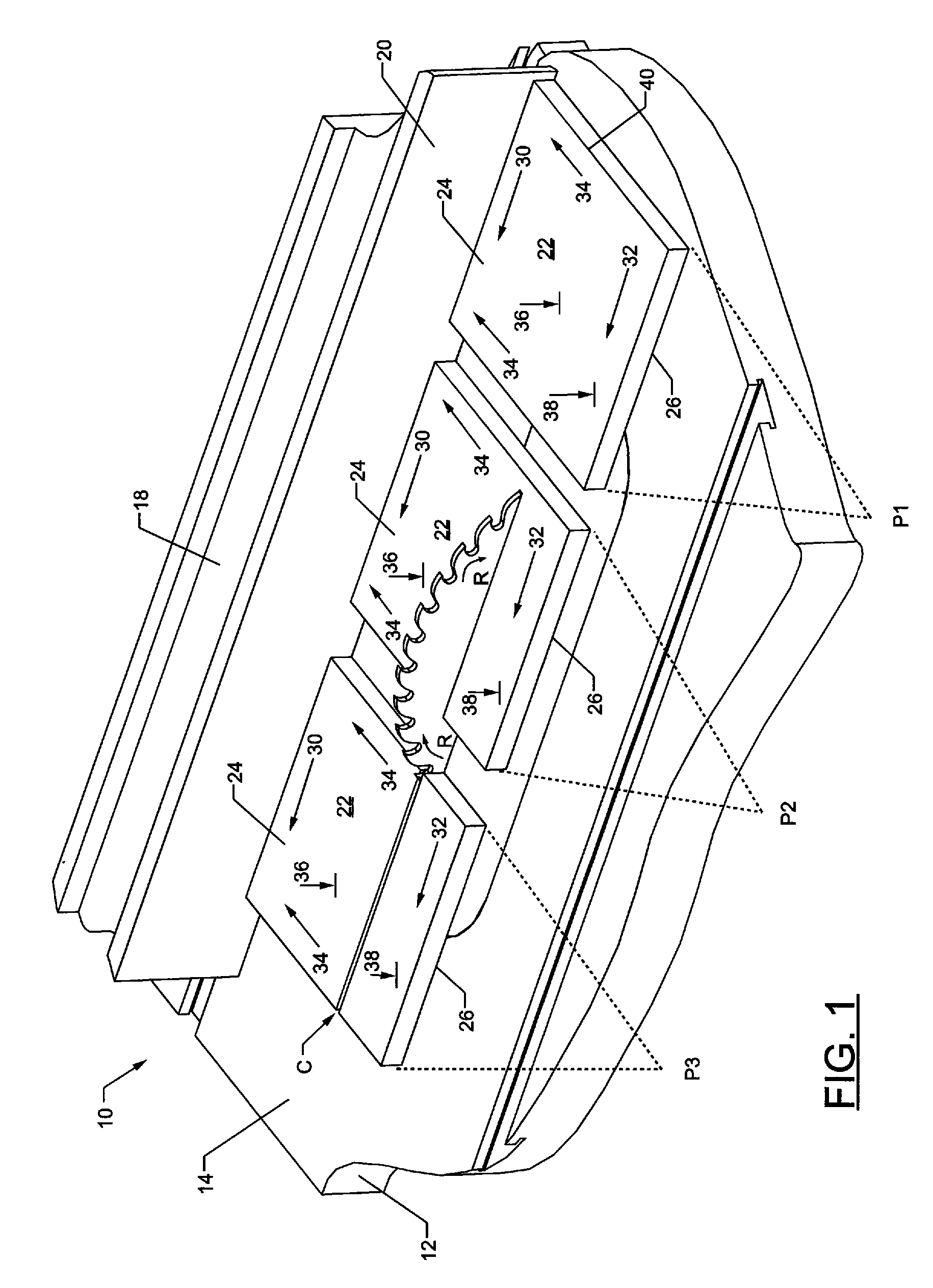
[0024] The inventor has analyzed the forces acting upon a work piece being moved over a table saw blade in order to identify the shortcomings of the prior art pusher designs and in order to evaluate the improved pusher apparatus described herein. FIG. 1 illustrates a table saw 10 including a table 12 with a flat horizontal surface 14 and a saw blade 16 having its top portion protruding above the table surface 14 through an opening formed in the table 12. A fence 18 connected to the table 12 includes a flat guide surface 20 oriented in a plane perpendicular to the table surface 14 and parallel to the saw blade 16. A work piece 22 is illustrated in three sequential positions P1, P2, P3 as it is moved past the saw blade 16. Position P1 illustrates the work piece 22 before it makes contact with the rotating saw blade 16. Position P2 illustrates the work piece 22 as it is being cut by the saw blade 16. Position P3 illustrates the work piece 22 as it is exiting the saw blade 16 after bein...


PUM

PropertyMeasurementUnit
diameteraaaaaaaaaa
widthaaaaaaaaaa
sizeaaaaaaaaaa

Abstract

An adjustable pushing apparatus (50) for safely moving a work piece (22) past a cutting tool (16). The apparatus includes a body (52), a first leg (56), a second leg (58) and a moveable center leg (60) defining a leg side surface (74) and two adjustable-width tunnels (62, 64) through which a cutting tool may pass. A handle (54) is moveable along a top surface (82) of the body to provide a balance of forces on both the inside cut portion (24) and the outside cut portion (26) of the work piece. Non-slip work piece-contacting surfaces (76) provide positive engagement with the work piece. A balance support device (84) may be attached to either the first or second leg at a plurality of vertical heights to balance the apparatus when the work piece is too narrow to make contact with a work piece-contacting surface on both side of the cut line (C). In one embodiment (200) a bridge handle (202) is used to maintain balanced forces on both sides of the cut line. The handle portion (204) may be longitudinally angled relative to the cut line to provide a force vector keeping the pushing apparatus and work piece secured against the table saw fence (16). A trailing edge heel (212) may be attached to the pusher to minimize blowout of the rearmost edge of the work piece and to assist in applying additional feeding force to the work piece.

Description

[0001] This application is a continuation-in-part and claims benefit of the Jan. 17, 2002 filing date of U.S. application Ser. No. 10 / 051,556, which in turn claims benefit of the Jun. 1, 2001, filing date of U.S. provisional patent application No. 60 / 295,378.FIELD OF THE INVENTION [0002] This invention relates generally to the field of woodworking tools, and more particularly to the field of accessories for feeding stock safely across a saw table. BACKGROUND OF THE INVENTION [0003] A table saw typically includes a flat, horizontally oriented table having an opening formed therein through which a top portion of a circular saw blade protrudes. The saw blade may be 10-12 inches in diameter, for example, and is motor driven to rotate at a speed of 3,000 revolutions per minute or more. A piece of stock material, typically wood, may be cut by moving it across the table to intersect the spinning saw blade. The height of the top of the saw blade above the table may be adjustable within pred...

Claims


Application Information

Patent Timeline
Patent Type & Authority Applications(United States)
IPC IPC(8): B23D59/00B27B25/10B27C5/06
CPCB27B25/10B27C5/06Y10T83/6638Y10T83/6657Y10T83/727Y10T83/773
Inventor WANG, HENRY
Owner WANG HENRY
Why Eureka
Try Eureka