Slide rack

a slide rack and slide technology, applied in the field of slide racks, can solve the problems of manual manipulation of the slide rack, relatively high cost of ball bearings or similar elements,

Inactive Publication Date: 2006-08-24
SSW HLDG
View PDF9 Cites 11 Cited by
  • Summary
  • Abstract
  • Description
  • Claims
  • Application Information

AI Technical Summary

Benefits of technology

[0016] When the cooking rack is in a retracted position on the base rack, ends of the rear brace of the cooking rack extend outwardly and under lateral angled pieces of the base rack. Lugs extend upwardly adjacent lateral angled braces of the base rack, and are intermediate to angled pieces and outer lateral braces of the base rack. When manual forces are exerted on a front of the cooking rack, so as to move the cooking rack in an extended movement, the rear brace of the cooking rack is positioned so that it remains below the lateral angled brace of the base rack, with the lugs being adjacent the angled braces. As the cooking rack is further

Problems solved by technology

One difficulty which has existed for a number of years in the industry relates to manual manipula

Method used


Image

  • Slide rack
  • Slide rack
  • Slide rack

Examples


first embodiment

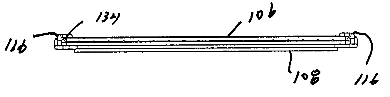
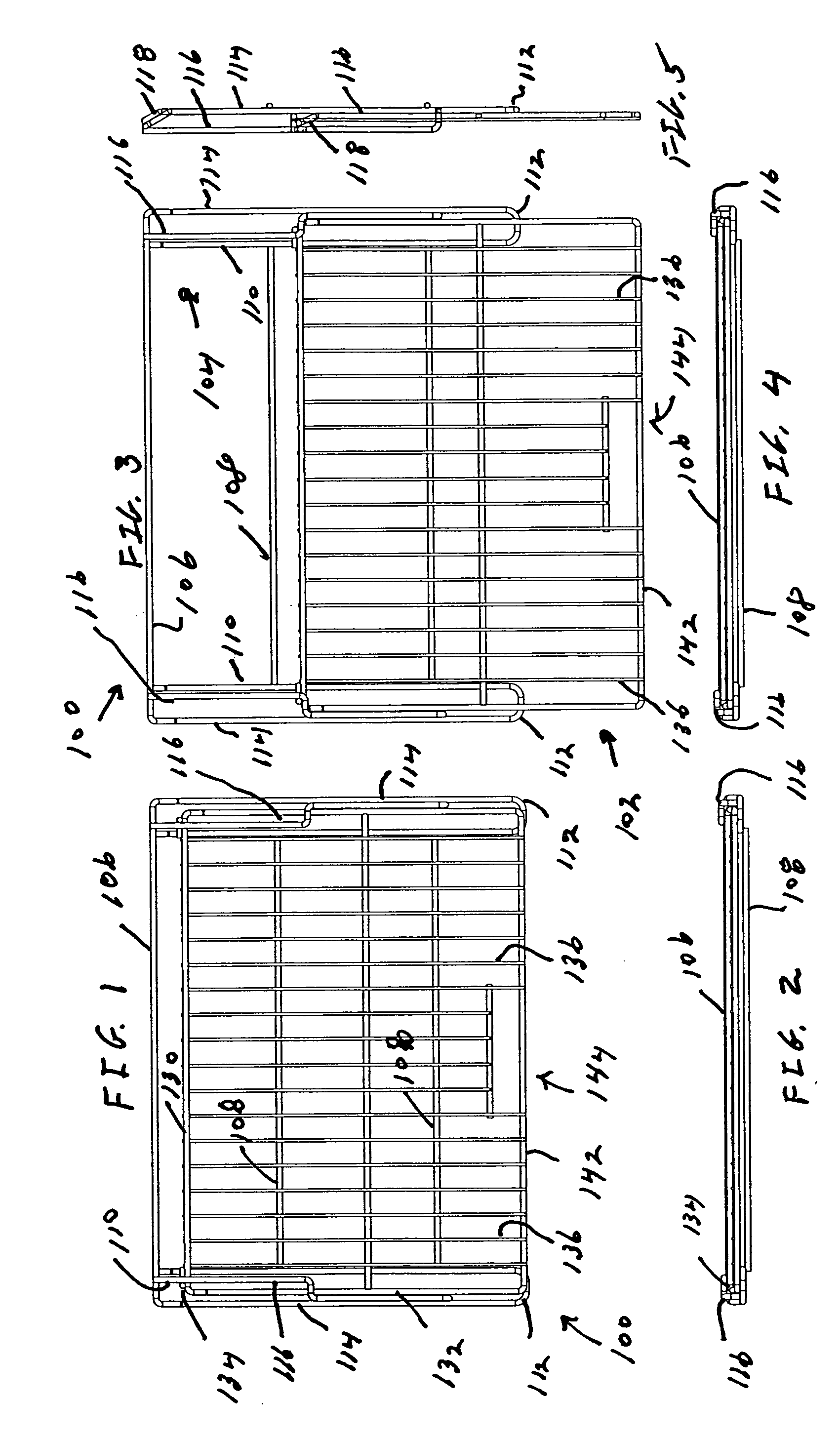
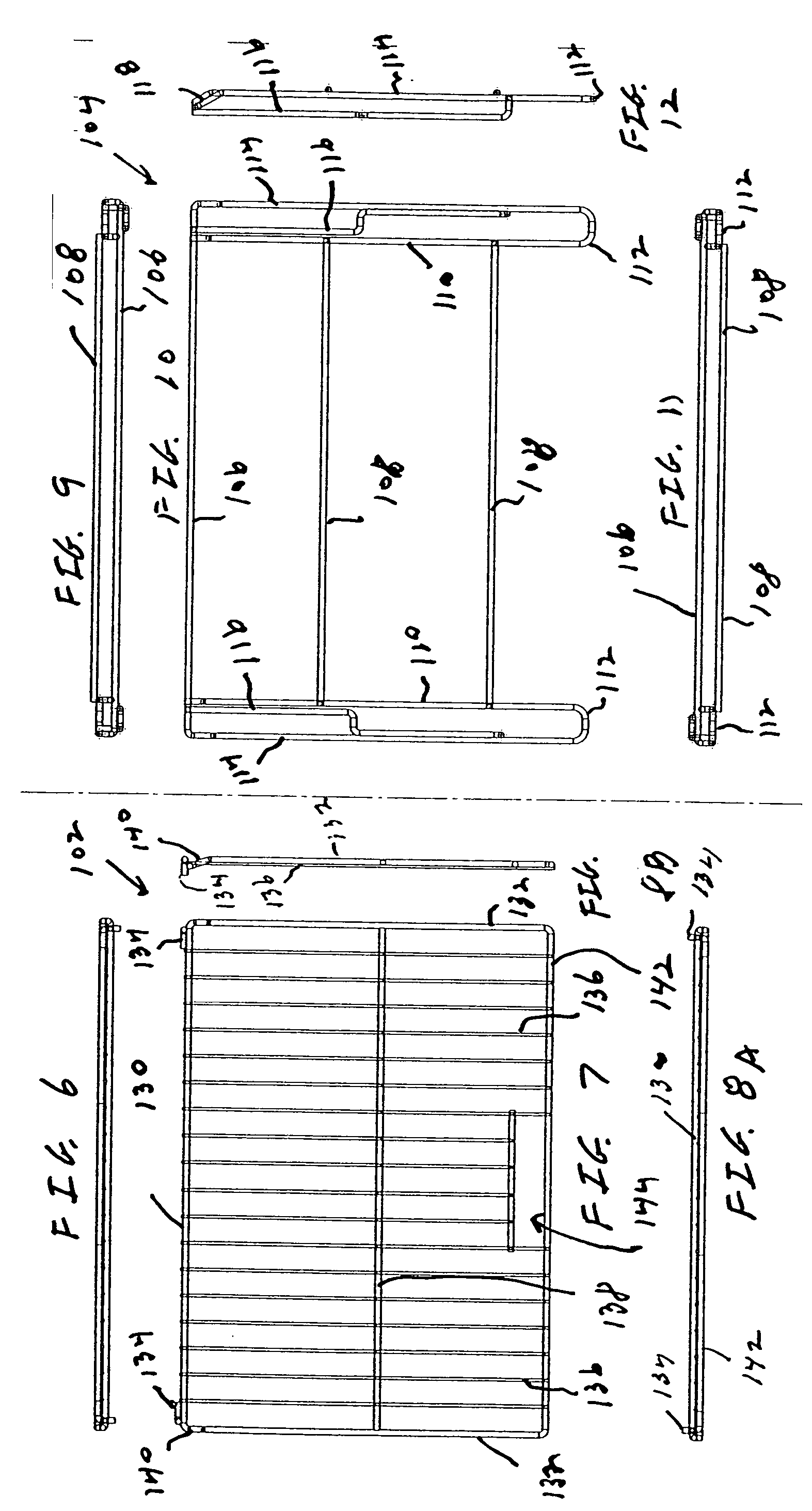
[0047] More specifically, and first with respect to FIGS. 1-12, a two piece oven rack 100 is illustrated in accordance with the invention. The two piece oven rack 100 includes a cooking rack 102 (shown in a stand alone configuration in FIGS. 7-8B) and a base rack 104 (shown in a stand alone configuration in FIGS. 9-12). Referring specifically to the base rack 104, the rack 104 includes an elongated rear brace 106 which extends horizontally along the back of the base rack 104. The elongated rear brace will be positioned adjacent the rear of the oven cavity. It should be emphasized that the base rack 104 is adapted to remain stationary and may be positioned on ledges or other protrusions associated with the inner liners of the oven cavities.

[0048] Parallel to the rear brace 106 and extending transversely across the base rack 104 near its middle and substantially near its front are a pair of transverse supports 108. Correspondingly, a pair of lateral supports 110 are also provided. The...

second embodiment

[0057] a slide rack in accordance with the invention is illustrated in FIGS. 13-24, and is identified as two piece oven rack 160. The two piece oven rack 160 is shown in the drawings as utilizing sheet metal components, rather than wire. Also, the two piece oven rack 160 has a slightly different configuration than the two piece oven rack 100 previously described herein. Both oven racks, however, provide for extension of a cooking rack relative to a base rack, and also provide a stop mechanism for the cooking rack during extension. It should also be mentioned that the oven racks may have various finishes, including, but not limited to nickel and porcelain. Also, as previously described, each of the oven racks may utilize a handle or the like, including the handle identified in U.S. Provisional patent application Ser. No. 60 / 496,885. Still further, the oven racks 100 and 160 may be utilized in conventional ovens, traditional household ranges, commercial ovens, barbeque grills and simi...


PUM


Abstract

An oven rack system has a two piece oven rack (100) with a cooking rack (102) and a base rack (104). The base rack (104) is adapted to remain stationary and may be positioned on ledges or other protrusions associated with inner liners of oven cavities. In one embodiment, a pair of angled pieces (118) extend between outer lateral braces (114) and a rear brace (106). The cooking rack (102) is adapted to slide on and be extendable relative to the base rack (104). The cooking rack (102) includes angled pieces (140) extending between the lateral braces (132) and the rear brace (130). A user can exert manual forces on the cooking rack (102) so as to move the cooking rack (102) in an extended or retracted position relative to the base rack (104). The movement occurs in the absence of the requirement of any type of ball bearings, rollers, or any other rotatable or rolling elements.

Description

CROSS-REFERENCE TO RELATED APPLICATIONS [0001] Not applicable. STATEMENT REGARDING FEDERALLY SPONSORED RESEARCH OR DEVELOPMENT [0002] Not applicable. REFERENCE TO A MICROFISHE APPENDIX [0003] Not applicable. BACKGROUND OF THE INVENTION [0004] 1. Field of the Invention [0005] The present invention relates to oven-related products and, more particularly, products in the form of oven racks having one portion of the rack capable of sliding relative to another portion of the rack. [0006] 2. Background Art [0007] Various types of oven racks are well known in the industry. For example, steel wire oven racks are often manufactured from a steel rod which is drawn, so as to form steel wire. These oven racks formed of steel wire products can be coated with various types of materials. Also, oven racks and other oven-related articles can be manufactured from products other than steel. Of course, any type of oven rack or similar product which is positioned within an oven cavity during use must be...

Claims


Application Information

Patent Timeline
IPC IPC(8): F24C15/16
CPCF24C15/16
Inventor METCALF, TIMOTHYMORTON, DAVID
Owner SSW HLDG
Why Eureka
Try Eureka