
Apparatus and method for making cellular shade material

a technology of cellular shade and apparatus, applied in the field of apparatus and a method for making cellular shade material, can solve the problem of processing further

Active Publication Date: 2006-08-24
TEH YOR CO LTD
View PDF21 Cites 23 Cited by
  • Summary
  • Abstract
  • Description
  • Claims
  • Application Information

AI Technical Summary

Benefits of technology

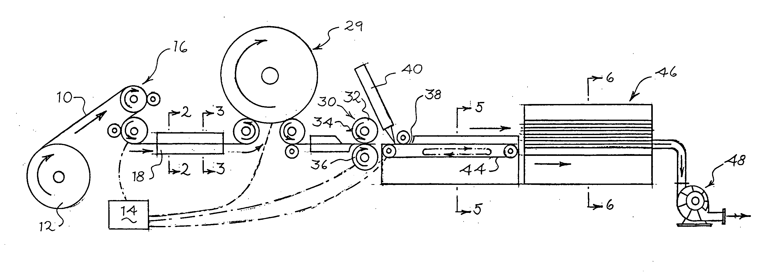
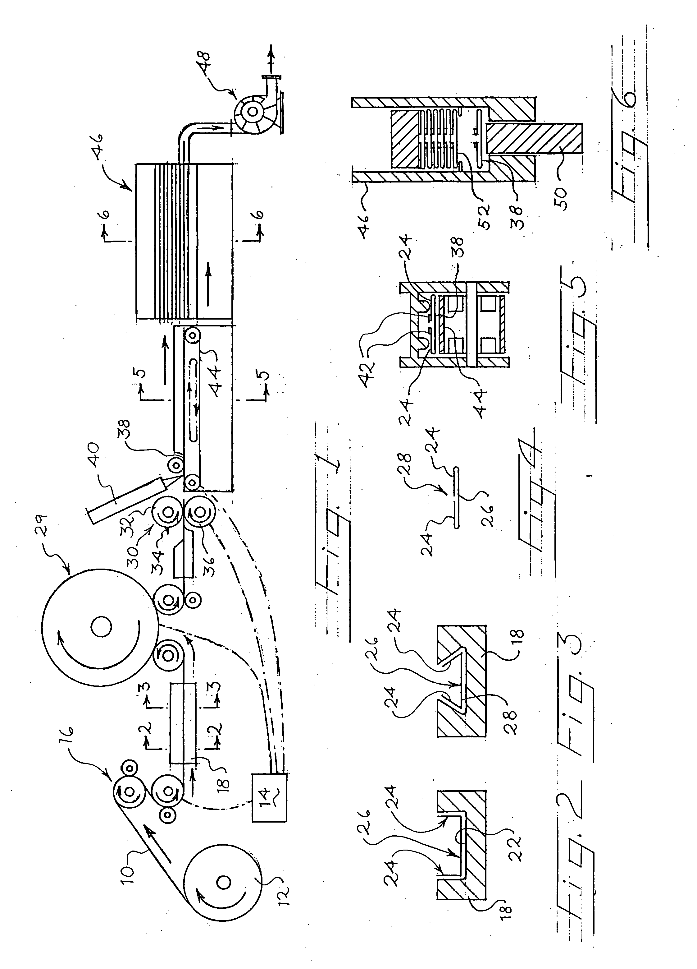
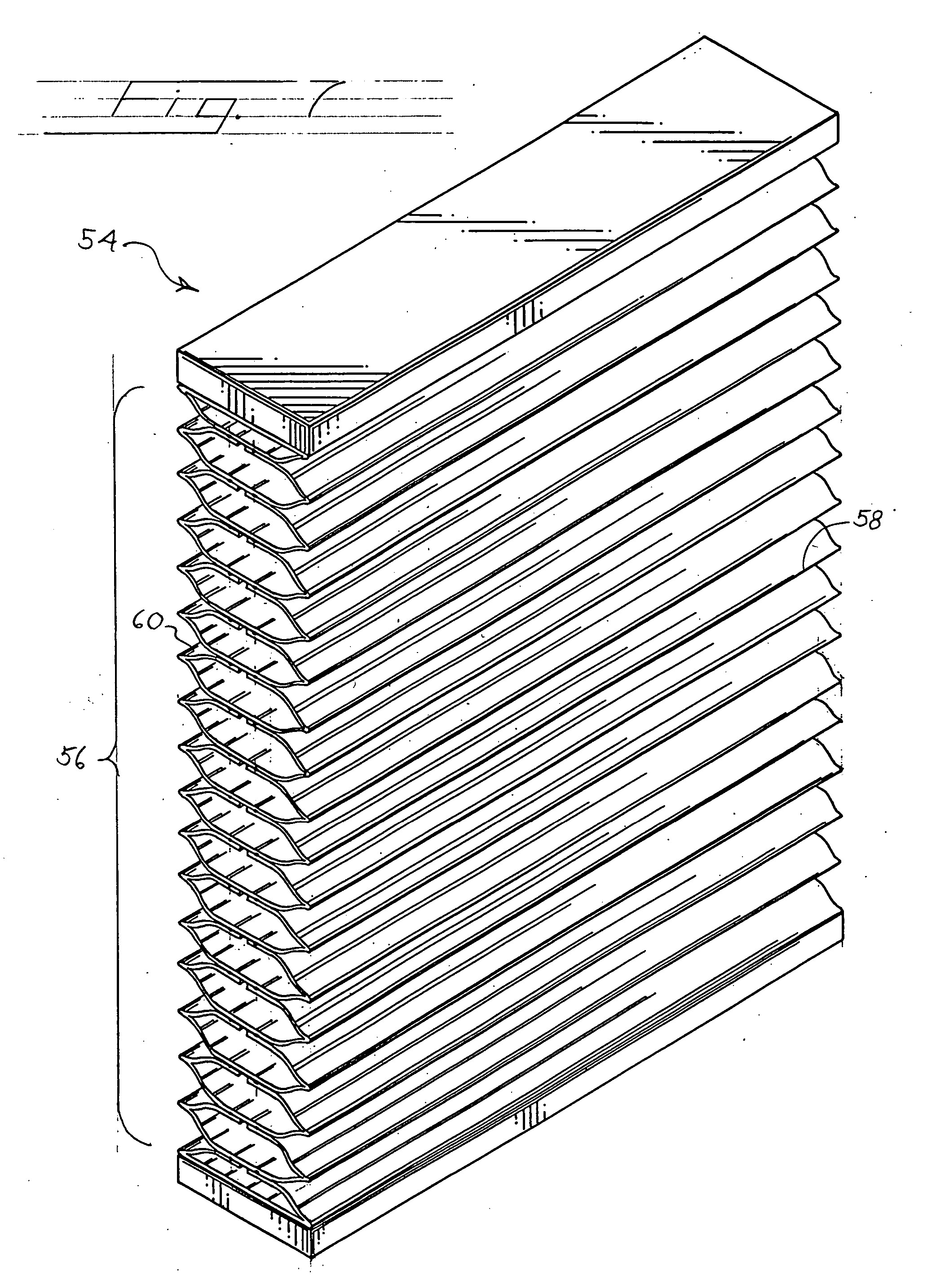
[0005] A method and apparatus for making an expandable honeycomb structure suitable for a window covering is provided. A continuous ribbon or strip of material, which is typically provided in the form of a roll, is provided by a series of feed rollers in operative communication with a drive mechanism downstream to a folder. The folder folds the continuous ribbon as it is conveyed therethrough to form a preform from the ribbon of material. The preform can be folded in a manner that will create one or more tubes defined by the single strip of material. Alternatively, the preform can be folded in a way that the strip, when adhered to other similarly formed strips, forms the cells of the honeycomb panel. The preform includes portions which are folded to overlap with other portions, such as a marginal portion folded over a main portion, such as a central portion. The preform can also be prefabricated such that it is provided to the cutter from a pre-made supply. In other words, the formation of the preform does not need to be completed in a continuous process with the other fabricating steps.
[0008] In some embodiments, the rate of progress of the row member into the stacker is increased. This can be accomplished through the use of a variety of components, however, it is preferred that an air flow device, such as a vacuum or a blower be used to urge the row member into the stacker.
[0009] One advantage of this embodiment over the methods and apparatus of the prior art such as disclosed above is a result of the positioning of the adhesive applicator. The prior art discloses the application of adhesive upstream of the cutter, and requires the additional step of cooling or heating the adhesive to dry or cure the adhesive so that adhesive residue on the cutter is reduced. Such an additional step is not required with the present invention. This is because the cutter is positioned upstream of the adhesive applicator. Accordingly, the process is more efficient since these additional curing steps are not required. For example, since the adhesive has not been cured, no additional heating or curing step is required to bond the row member to other row members in the stack. The present invention also requires less downtime to clean or replace cutter and roller components befouled with adhesive residue.

Problems solved by technology

One disadvantage with such a process and apparatus is that since the adhesive is applied to the strip of material before cutting, the process requires the further step of chilling or heating the material after the adhesive has been applied to dry or cure the adhesive.
One problem with this process is that a web is provided, which is folded and stacked, and therefore, different width webs must be utilized for different width window coverings.

Method used


Image

  • Apparatus and method for making cellular shade material
  • Apparatus and method for making cellular shade material
  • Apparatus and method for making cellular shade material

Examples


Embodiment Construction

[0032] The invention disclosed herein is susceptible of embodiment in many different forms. Shown in the drawings and described hereinbelow in detail are preferred embodiments of the invention. It is to be understood, however, that the present disclosure is an exemplification of the principles of the invention and does not limit the invention to the illustrated embodiments.

[0033]FIGS. 1-6 illustrate a preferred embodiment of the method and apparatus according to the present invention. A continuous ribbon or strip of material 10 is typically provided in the form of a roll 12. A drive mechanism operatively connected to a series of feed rollers 16, shown schematically as box 14, continuously pulls the material 10 off of the roll 12 and conveys the material 10 downstream to a folder 18. The material 10 is folded by the progression of the material 10 through the folder 18 to form a preform. For example, as shown in FIGS. 2 and 3, the material 10 is folded as it passes through channel 22...


PUM

PropertyMeasurementUnit
Adhesivityaaaaaaaaaa

Abstract

An apparatus and method for making expandable honeycomb structures suitable for use as window coverings is provided. Material is fed to a folder and past a cutter. Adhesive is applied to the material downstream of the cutter and the material is cut to desired lengths. The cut strips of material are stacked with similarly formed strips to form the honeycomb structure.

Description

TECHNICAL FIELD OF THE INVENTION [0001] This invention relates to an improved apparatus and a method for making a cellular shade material. BACKGROUND OF THE INVENTION [0002] One well-known type of window treatment is the honeycomb window shade. In a honeycomb window shade is made up of an interconnected series of rows of cells of a thin foldable material suspended from a headrail. There are a variety of apparatus and methods known in the art for manufacturing such honeycomb shades. One technique, disclosed in U.S. Pat. No. 4,450,027 to Colson, involves folding a continuous strip of fabric into a tube, applying adhesive to the exterior of the tube and then winding the tube onto a rotating rack so that the adjacent windings of the stacked tube are bonded together to form a honeycomb array or stack of cells. The stacked array of cells is then cut and the cellular structure removed from the tube. U.S. Pat. No. 5,228,936 and U.S. Pat. No. 5,714,034 to Goodhue is directed to another appar...

Claims


Application Information

Patent Timeline
IPC IPC(8): B32B37/12B32B37/30B32B38/04B32B38/00B32B37/18
CPCB31D3/023E06B9/262E06B9/266E06B2009/2627Y10T156/1749Y10T156/1069Y10T156/1798Y10T156/13Y10T156/1075Y10T156/1003Y10T156/1051Y10T156/1751Y10T156/1056B32B37/18B32B37/30B32B38/00
Inventor YU, FU-LAI
Owner TEH YOR CO LTD
Learn More