
Heat exchanger

a technology of heat exchanger and corrugated fin, which is applied in the direction of heat exchange apparatus safety devices, lighting and heating equipment, and stationary conduit assemblies, etc., can solve the problems of corrugated fin buckling and and achieve the effect of suppressing the fin buckling and the core unit assembly dimensional error

Inactive Publication Date: 2006-08-24
DENSO CORP
View PDF5 Cites 12 Cited by
  • Summary
  • Abstract
  • Description
  • Claims
  • Application Information

AI Technical Summary

Benefits of technology

[0010] In view of the points described above, the object of this invention is to suppress buckling of the fins and a dimensional error of the core unit assembly.
[0012] According to one aspect of this invention, there is provided a heat exchanger in which in the case where the base portion tends to be displaced or the whole side plates tend to be twisted, a hook comes into contact with the deformed portion thereby to suppress or prevent the displacement of the base portion and the twisting of the side plates, thereby suppressing or preventing buckling of the fins and a dimensional error of the core unit assembly.

Problems solved by technology

At the time of assembly before the integrating brazing process, therefore, the base portion 41 is liable to be displaced and the side plates 4 are easily twisted, thereby leading to the problem of buckling of the corrugated fins 11 and a dimensional error of the core unit assembly.

Method used


Image

  • Heat exchanger
  • Heat exchanger
  • Heat exchanger

Examples


Embodiment Construction

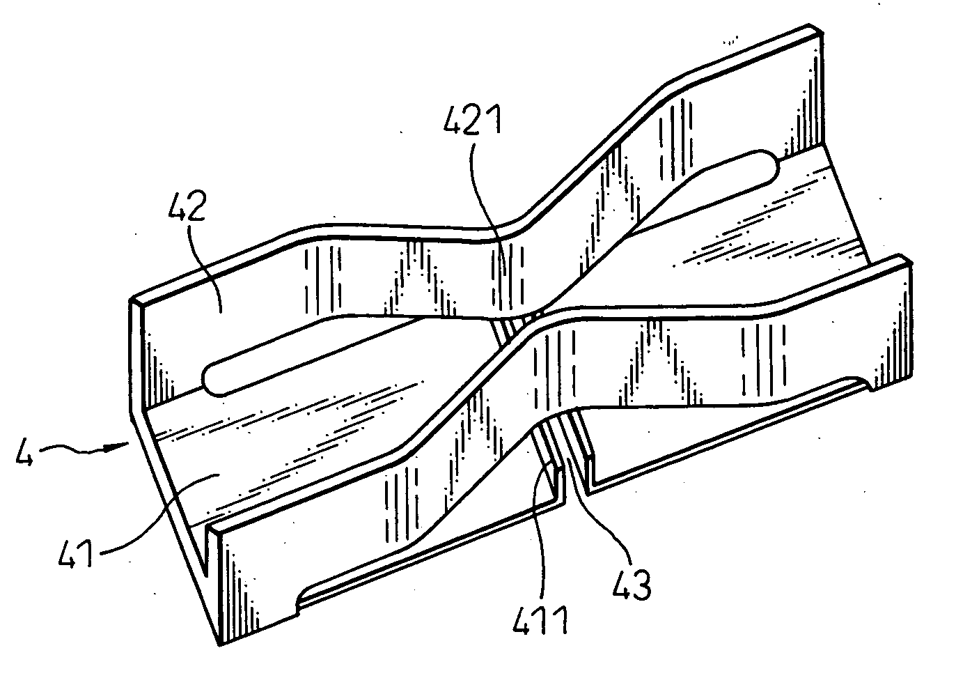
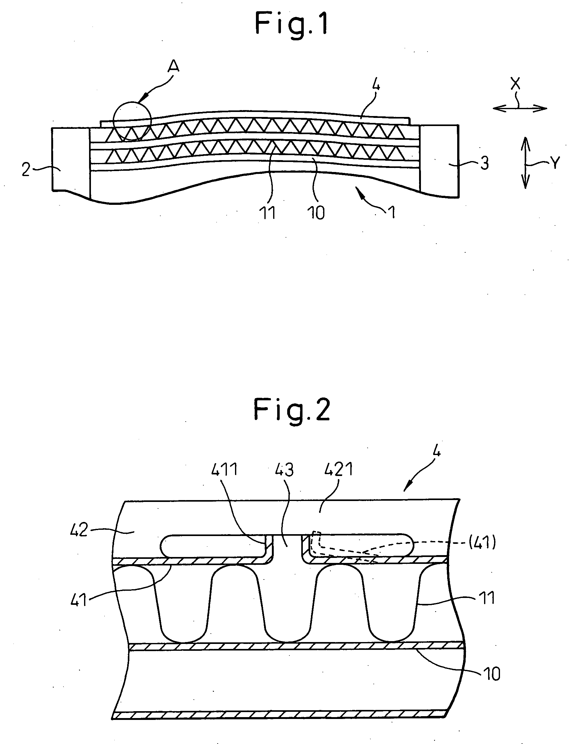
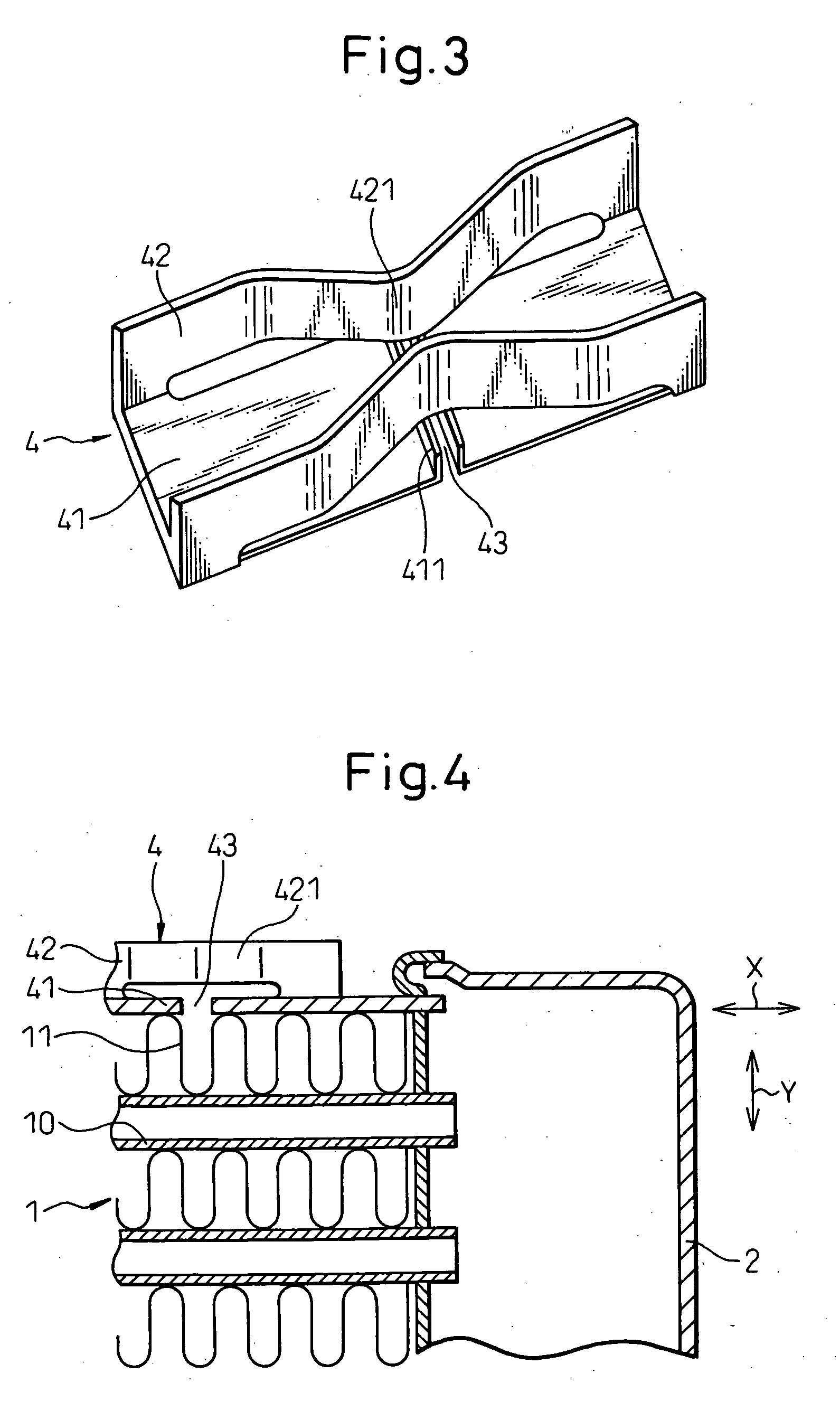
[0022] An embodiment of this invention is explained below. This embodiment represents an application of the heat exchanger according to the invention to the intercooler for cooling the supercharged air introduced into the internal combustion engine. FIG. 1 is a front view of the heat exchanger according to an embodiment, FIG. 2 an enlarged front view showing the portion A in FIG. 1, and FIG. 3 a perspective view of the side plate 4 in FIG. 1.

[0023] As shown in FIG. 1, the heat exchanger includes a parallelopipedal core unit 1 configured of a multiplicity of tubes 10 and a multiplicity of corrugated fins 11 stacked in alternate layers.

[0024] The tubes 10 are flat brass members having an internal path in which the supercharged air introduced into the internal combustion engine mounted on an automotive vehicle flows. The corrugated fins 11 are made of copper and are corrugated to promote the heat exchange between the supercharged air and the cool air.

[0025] Tanks 2, 3 communicating ...


PUM


Abstract

A heat exchanger is disclosed. Side plates (4) each include a base portion (41), in contact with fins (11), and side wall portions (42) extending from the base portion (41) in the direction Y in which tubes (10) are stacked. The side wall portions (42) are formed with a bent deforming portion (421) to facilitate extension / shrinkage, of the side wall portions (42), in the longitudinal direction (X) of the tubes (10). The base portion (41) is formed with a pair of hooks (411) extending toward the surface of the bent deforming portion (421) in opposed relation to the base portion (41). In the case where the base portion (41) tends to be displaced, the hooks (411) come into contact with the bent deforming portion (421) to thereby suppress or prevent the displacement of the base portion (41).

Description

BACKGROUND OF THE INVENTION [0001] 1. Field of the Invention [0002] This invention relates to a heat exchanger for exchanging heat between fluids, which is effectively applicable to an intercooler for cooling the air (supercharged air) introduced into an internal combustion engine, for example, and is supercharged for combustion. [0003] 2. Description of the Related Art [0004] The conventional heat exchanger, as shown in FIGS. 4, 5, is configured of a multiplicity of tubes 10 and a multiplicity of corrugated fins 11 stacked alternately with each other to make up a core unit 1. Also, tanks 2, 3 are arranged at the two ends in the longitudinal direction X of the tubes in the core unit 1, and side plates 4 are arranged at the two ends in the direction Y in which the tubes are stacked in the core unit 1. [0005] This heat exchanger is assembled in such a manner that the component parts of the heat exchanger are assembled provisionally into a predetermined heat exchanger structure, after ...

Claims


Application Information

Patent Timeline
Patent Type & Authority Applications(United States)
IPC IPC(8): F28F9/007
CPCF28F9/001F28F2265/26
Inventor HARADA, MASAKI
Owner DENSO CORP
Learn More