Air spring and jounce shock assembly
a technology of air spring and shock assembly, which is applied in the direction of shock absorbers, mechanical equipment, transportation and packaging, etc., can solve the problems of increasing the complexity of the assembly reducing the efficiency of the suspension system, and requiring a large amount, so as to reduce the complexity of the assembly and reduce the packaging space. , the effect of reducing the complexity of the vehicl
- Summary
- Abstract
- Description
- Claims
- Application Information
AI Technical Summary
Benefits of technology
Problems solved by technology
Method used
Image
Examples
second embodiment
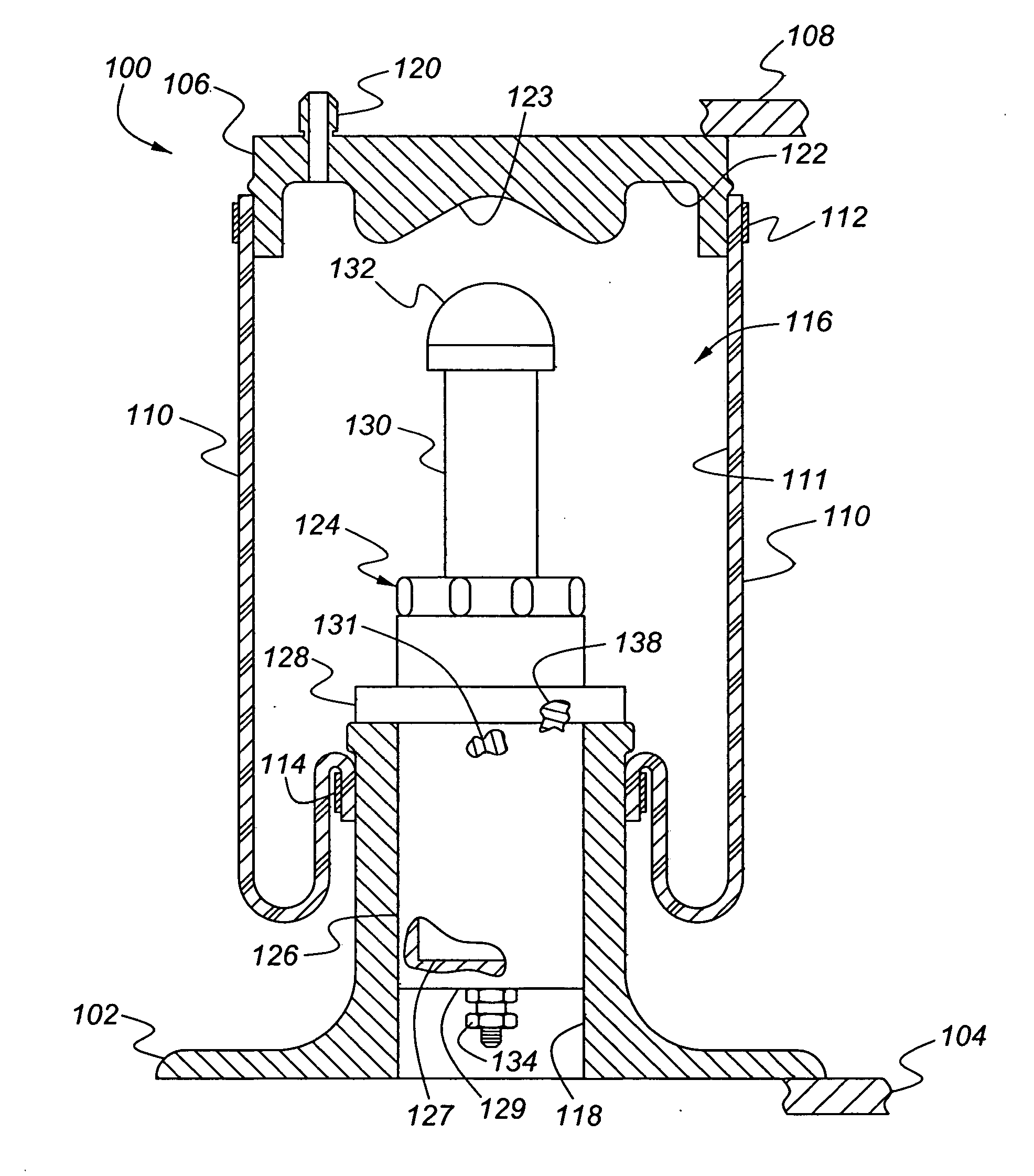
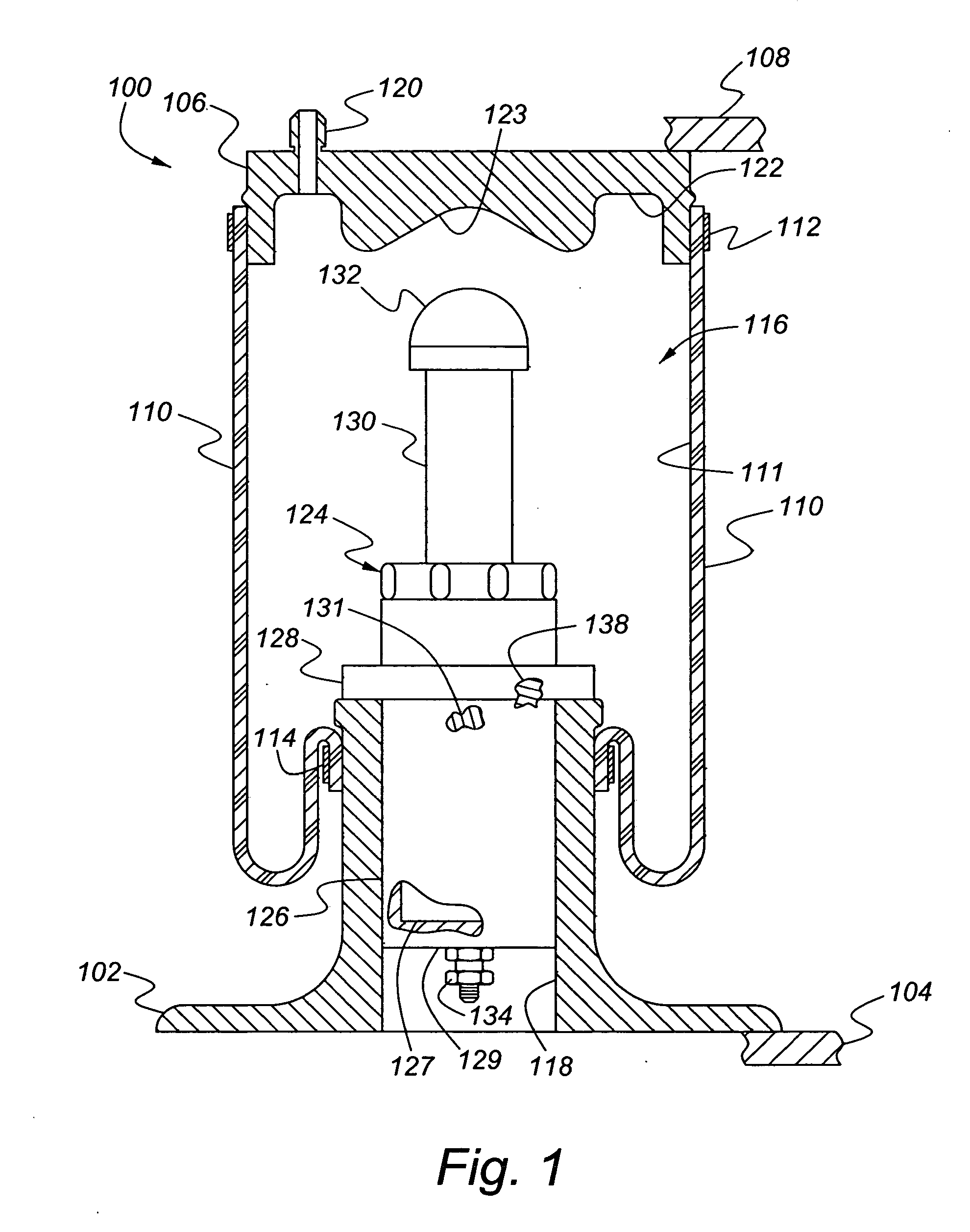
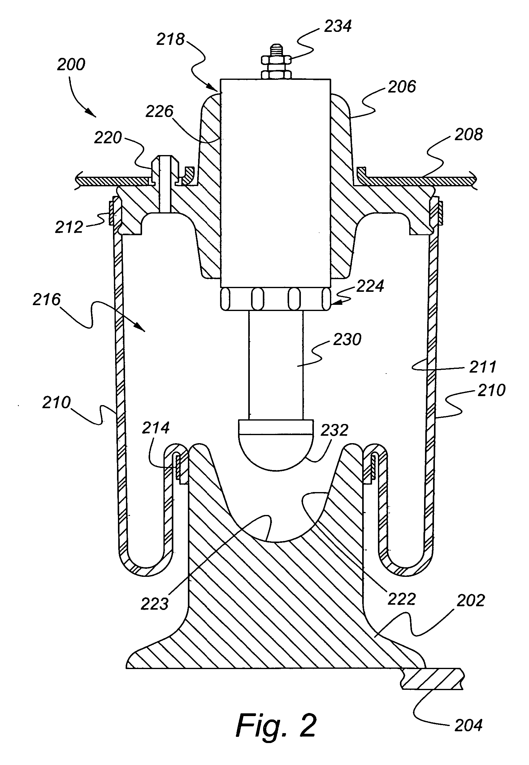
[0022] Referring now to FIG. 2, an air spring and jounce shock assembly in accordance with the present invention is indicated generally at 200. The assembly 200 includes an air spring base 202 that is attached to a vehicle axle assembly (or other suspension component, such as a control arm) 204. The assembly 200 also includes an air spring top cap 206 that is attached to a vehicle frame 208. An air spring diaphragm 210 is attached to and seals between the base 202 and the top cap 206. The diaphragm 210 includes an inner surface 211 that defines a compressed air cavity 216 between the base 202 and the top cap 206. The diaphragm 210 is preferably attached to the top cap 206 at an upper edge thereof by an upper clamp or spring 212 and to the base 202 by a lower clamp or spring 214 at a lower edge thereof. The top cap 206 includes an air feed line 220 extending therethrough that is connected to a source of compressed air (not shown).
[0023] The air spring top cap 206 includes a support 2...
first embodiment
[0026] The operation of the air spring and jounce shock assembly 200 is similar to that of the As the vehicle is driven under normal loading along relatively smooth terrain, the axle assembly 204 and frame 208 will move relative to one another, compressing and decompressing the air in the compressed air cavity 216, which supports the top cap 206 relative to the base 202. The jounce shock assembly 224 is sized and positioned so that the rod cap 232 remains spaced from the reaction surface 222 during the normal loading conditions. Accordingly, the air spring and jounce shock assembly 200 acts essentially as a conventional air spring under these driving conditions.
[0027] On the other hand, when the vehicle encounters terrain that causes a large energy input from an impact—such as a pothole or a curb—the air spring diaphragm 210 may allow the axle assembly 204 to drive the base 202 toward the top cap 206 and frame 208 to an extent that the rod cap 232 contacts the reaction surface 222....
third embodiment
[0028] Referring now to FIG. 3, an air spring and jounce shock assembly in accordance with the present invention is indicated generally at 300. The assembly 300 includes an air spring base 302 that is attached to a vehicle axle assembly (or other suspension component, such as a control arm) 304. The assembly 300 also includes an air spring top cap 306 that is attached to a vehicle frame 308. An air spring diaphragm 310 is attached to and seals between the base 302 and the top cap 306. The diaphragm 310 includes an inner surface 311 that defines a compressed air cavity 316 between the base 302 and the top cap 306. The diaphragm 310 is preferably attached to the top cap 306 at an upper edge thereof by an upper clamp or spring (not shown in FIG. 3) and to the base 302 by a lower clamp or spring (not shown in FIG. 3) at a lower edge thereof. The top cap 306 includes an air feed line 320 extending therethrough that is connected to a source of compressed air (not shown).
[0029] The air spr...
PUM
 Abstract
Description
Claims
Application Information
 - R&D
- Intellectual Property
- Life Sciences
- Materials
- Tech Scout
- Unparalleled Data Quality
- Higher Quality Content
- 60% Fewer Hallucinations
Browse by: Latest US Patents, China's latest patents, Technical Efficacy Thesaurus, Application Domain, Technology Topic, Popular Technical Reports.
© 2025 PatSnap. All rights reserved.Legal|Privacy policy|Modern Slavery Act Transparency Statement|Sitemap|About US| Contact US: help@patsnap.com


