Method and apparatus for magnetic field detection

a magnetic field and detection method technology, applied in the direction of magnetic field measurement using superconductive devices, instruments, dissimilar materials junction devices, etc., can solve the problems of inability to provide data about the absolute value of the magnetic field or gradient, gate drift and noise, and low frequency accuracy of state of the art gradiometers, etc., to facilitate separation of these effects, effective vibration isolation, and easy engineering

Active Publication Date: 2006-08-24
COMMONWEALTH SCI & IND RES ORG
View PDF4 Cites 13 Cited by
  • Summary
  • Abstract
  • Description
  • Claims
  • Application Information

AI Technical Summary

Benefits of technology

[0027] While the use of an axial gradiometer may be favoured in implementations of the present invention because of its intrinsic noise immunity, the advantages of rotating a gradiometer are not limited to the axial configuration.
[0039] Embodiments of the third and fourth aspects of the invention effectively provide a single measurement of the true value of each of the three off-diagonal components of the gradient tensor, three measurements of the diagonal components and two measurements of each of the field components. Because more than the minimum of five tensor components are obtained, the use of just three such rotating gradiometers in fact provides a redundant measurement. This redundancy permits a least-squares best fit solution, further improving the quality of data obtained. Any DC offsets such as low frequency drift in flux gates or the fixed offset of a SQUID, for example, can also be determined and monitored to provide information about the operating conditions of the detectors. Such offsets can also be separated from gradient data in the Fourier domain.
[0043] Further, since the external gradient and field are modulated by the rotation, but DC offsets, drift or very low frequency noise in the detectors are not, the rotation provided by the present invention facilitates separation of the these effects in the Fourier domain so that the DC and low frequency performance of the instrument is not limited by the performance of the detectors in these respects.
[0044] Furthermore, in the case of magnetic gradiometry, if the gradiometer is to be employed in a moving platform such as an aircraft, for example, a suspension system is generally used to isolate the instrument from vibrations which would otherwise induce significant noise by moving the instrument in the earth's magnetic field. However, in previous systems, such suspension systems have proven to be extremely difficult to engineer as significant isolation is required at sub 1 Hz frequencies. However, the rotating gradiometer provided by present invention modulates low frequency signals with the rotation frequency, thus facilitating the use of suspension systems which then only need to provide effective vibration isolation near the fundamental and first overtone of the rotation frequency. Such suspension systems are typically significantly easier to engineer than sub-1 Hz suspension systems.
[0045] In preferred embodiments of the third and fourth aspects of the invention, the at least three gradiometers are rotated at differing frequencies. Such embodiments of the invention facilitate separation of the frequency of operation of each gradiometer, and further facilitate a reduction in “cross-talk” between the respective gradiometers, of the type set out in the preceding discussion. As such cross-talk effects will be occurring at differing frequencies, the effect of one gradiometer operation on another can be filtered out or removed in the frequency domain.
[0046] Accordingly, preferred embodiments of the present invention may yield significant advantages over previous field detection devices and methods in a number of ways. First, rotation of the gradiometer breaks the nexus between engineering tolerances (in positioning two sensors in precisely parallel planes) and the ultimate CMRR performance. Further, providing three rotating gradiometers in accordance with embodiments of the third and fourth aspects of the present invention yields measurements of all five components of the gradient tensor and all three the components of the field, with redundancy in the data, all by using only 3 field detectors. Additionally, the rotation of the gradiometer breaks the dependence of the DC performance of the instrument on the DC performance of the detectors. Embodiments of the present invention also facilitate absolute value measurements of both the gradient and field components using SQUIDs. Embodiments of the present invention may also provide real time information of the condition of the SQUID in operation, for example as to whether or not the SQUID has remained in lock. As noted in the preceding discussions, previous SQUID devices have only been capable of making relative field measurements, not absolute field measurements. Furthermore, embodiments of the present invention may improve the sensitivity of field detection by shifting the working point of the detectors to a higher frequency, where the noise performance of the detectors and the vibration isolation afforded by suspension systems is superior. Yet further, certain embodiments of the present invention can serve to reduce the effects of cross-talk by use of distinguishable rotation frequencies.

Problems solved by technology

Further, the DC and low frequency accuracy of state of the art gradiometers is limited by the DC and drift performance of the field detectors employed, and is also limited by the low frequency noise performance of the field detectors.
Flux gates have considerable drift and noise in comparison to SQUIDs, but state of the art SQUID systems are incapable of providing data about the absolute value of the magnetic field or gradient.
The SQUID, therefore, is not an absolute field detector and state of the art gradiometers cannot provide absolute value measurements of the gradient components.
A further problem arises in tensor gradiometers.
However, a problem which arises from the use of a plurality of field sensors or gradiometers to measure the gradient components, is that the sensors or gradiometers distort the field in their neighbourhood.
Consequently, each sensor or gradiometer adversely affects the measurement of the field by the other sensors or gradiometers which are deployed to measure other gradient components.
Such a “cross-talk” effect limits the accuracy of the gradient measurement.

Method used


Image

  • Method and apparatus for magnetic field detection
  • Method and apparatus for magnetic field detection
  • Method and apparatus for magnetic field detection

Examples


Embodiment Construction

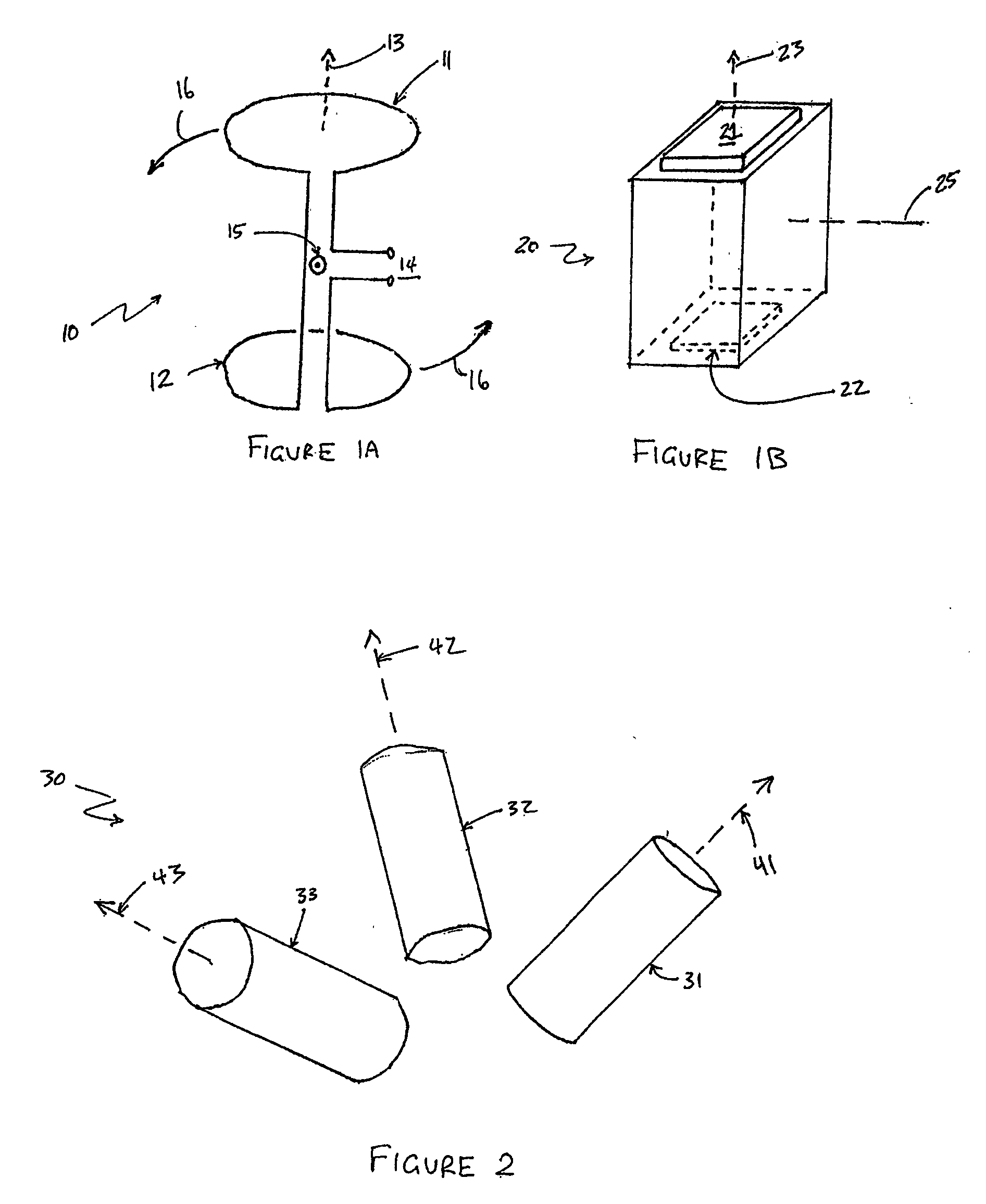
[0051]FIG. 1a illustrates a low temperature superconducting gradiometer 10 in accordance with the present invention. Gradiometer 10 comprises a first field vector sensor in the form of superconducting wire loop 11. Gradiometer 10 further comprises a second field vector sensor in the form of superconducting wire loop 12. Sensors 11 and 12 are positioned substantially coaxially so as to sense field vectors along axis 13. Further, sensors 11 and 12 are connected in a differencing arrangement, whereby a signal produced at terminals 14 stems from the difference between the magnetic field vectors sensed by sensors 11 and 12. In accordance with the present invention, gradiometer 10 is configured to rotate about axis 15, which is at a normal to the page as viewed in FIG. 1a. Rotation of the gradiometer is indicated by direction arrows 16.

[0052]FIG. 1b illustrates a high temperature superconducting gradiometer 20 in accordance with the present invention. Gradiometer 20 comprises a first fie...


PUM

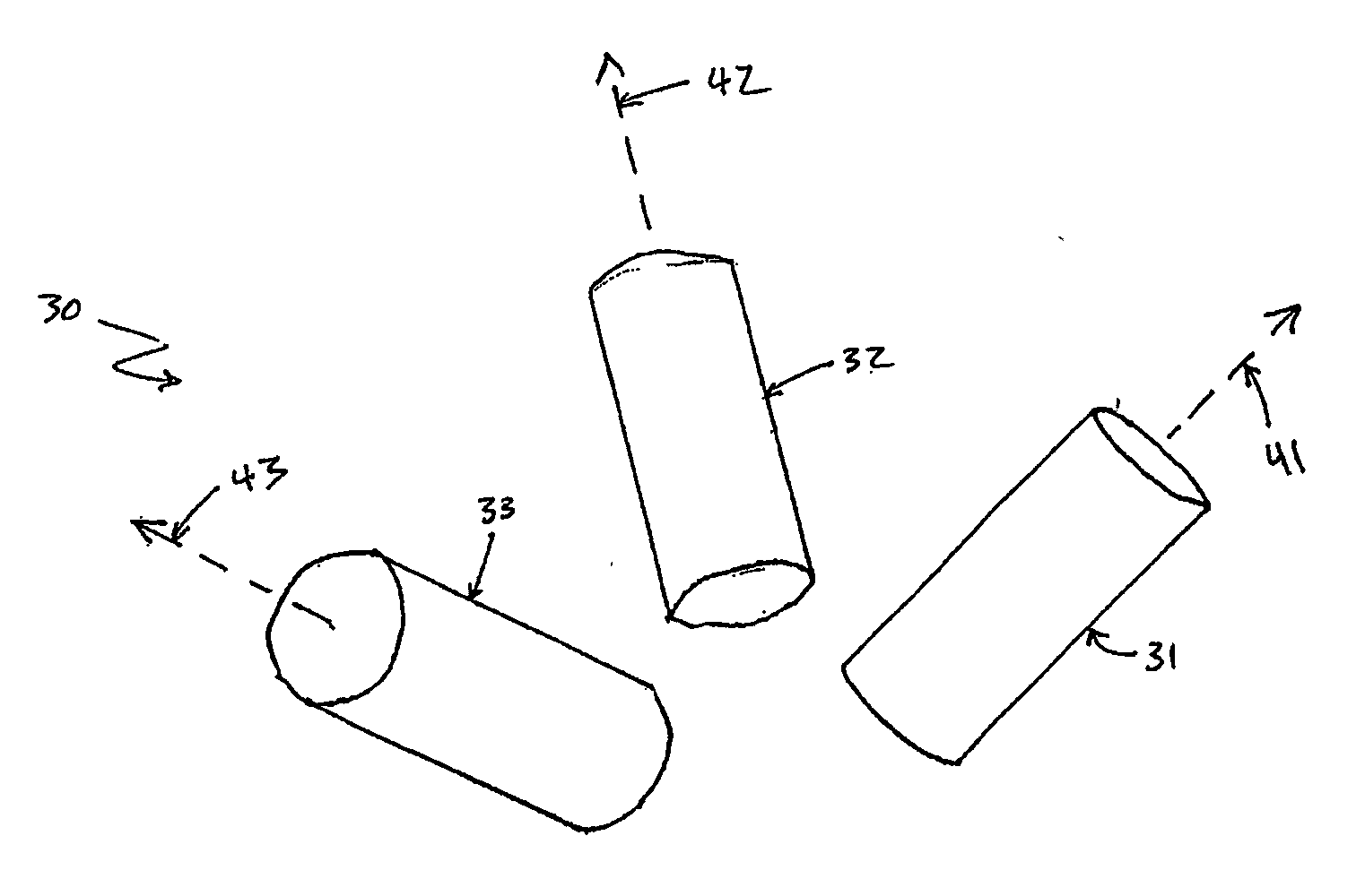

Abstract

A method and device for field detection are provided, in which one or more gradiometers (31, 32, 33) are positioned in the field and rotated about their axes. Rotation of a single gradiometer allows an output signal of the gradiometer to be analysed in the Fourier domain, which allows particular field components to be obtained, and also separates the field signal from noise, in the frequency domain. Use of three such rotating gradiometers with non-parallel axes allows a complete magnetic field gradient tensor to be obtained with data redundancy, and can reduce crosstalk.

Description

TECHNICAL FIELD [0001] The present invention relates to a method and apparatus for measurement of a magnetic field, and in particular relates to rotating a magnetic sensor relative to the magnetic field to be measured. BACKGROUND ART [0002] A gradiometer is a device for measuring the difference between two signals, with an aim to facilitate rejection of common mode noise signals and improved reduction in errors that arise from misorientation of the measuring instrument. [0003] The ability of a gradiometer to measure small magnetic field gradients in the presence of a large background magnetic field is determined by its ability to reject large common mode signals, and the intrinsic noise and drift performance of the field detectors employed. The first of these characteristics is called the common mode rejection ratio (CMRR). In conventional gradiometers the CMRR is determined by the precision with which the field sensors comprising the gradiometer are balanced. That is, the CMRR is d...

Claims


Application Information

Patent Timeline
Patent Type & Authority Applications(United States)
IPC IPC(8): G01R33/02G01R33/022G01R33/035G01R33/04H01L39/22H01L39/24
CPCG01R33/0356Y10S505/846
Inventor TILBROOK, DAVID LOUIS
Owner COMMONWEALTH SCI & IND RES ORG
Why Eureka
Try Eureka