
Method and apparatus for designing force sensations in force feedback computer applications

a technology of force sensation and computer application, applied in the field of interface devices, can solve the problems of cumbersome methods and the difficulty of force sensation designers in integrating these types of sensations into software applications

Inactive Publication Date: 2006-08-24
IMMERSION CORPORATION
View PDF6 Cites 52 Cited by
  • Summary
  • Abstract
  • Description
  • Claims
  • Application Information

AI Technical Summary

Benefits of technology

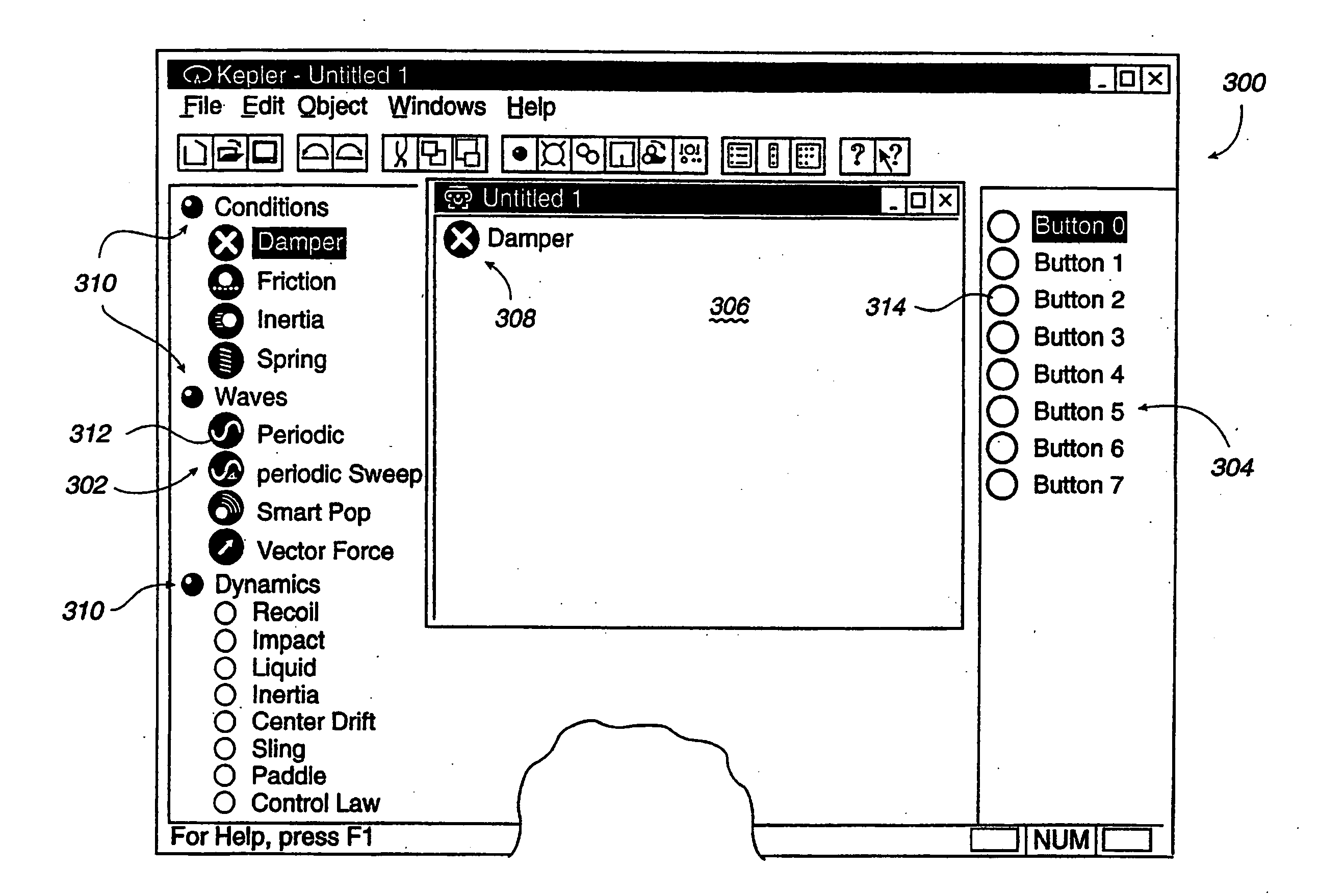
[0006] The present invention is directed to designing force sensations output by a force feedback interface device. A controlling host computer provides a design interface tool that allows intuitive and simple design of a variety of force sensations.
[0009] The present invention advantageously provides a simple, easy-to-use design interface tool for designing force feedback sensations. Given the large variety of possible force sensations and the often unexpected results when modifying the several parameters of force sensations, the design interface tool of the present invention meets the needs of force sensation designers that wish to create force sensations as close to their needs as possible. The graphical design interface of the present invention allows a force sensation programmer or developer to easily and intuitively design force sensations, conveniently experience the designed force sensations, and visually understand the effect of changes to different aspects of the force sensations.

Problems solved by technology

A problem with the prior art development of force feedback sensations in software is that the programmer of force feedback applications does not have an intuitive sense as to how forces will feel when adjusted in certain ways, and thus must go to great effort to develop characteristics of forces that are desired for a specific application.
This method is cumbersome because it is often not intuitive how a parameter will affect the feel of a force as it is actually output on the user object; the programmer often may not even be close to the desired force sensation with initial parameter settings.
Other types of forces may not be intuitive at all, such as a spring having a negative stiffness, and thus force sensation designers may have a difficult time integrating these types of sensations into software applications.

Method used


Image

  • Method and apparatus for designing force sensations in force feedback computer applications
  • Method and apparatus for designing force sensations in force feedback computer applications
  • Method and apparatus for designing force sensations in force feedback computer applications

Examples


Embodiment Construction

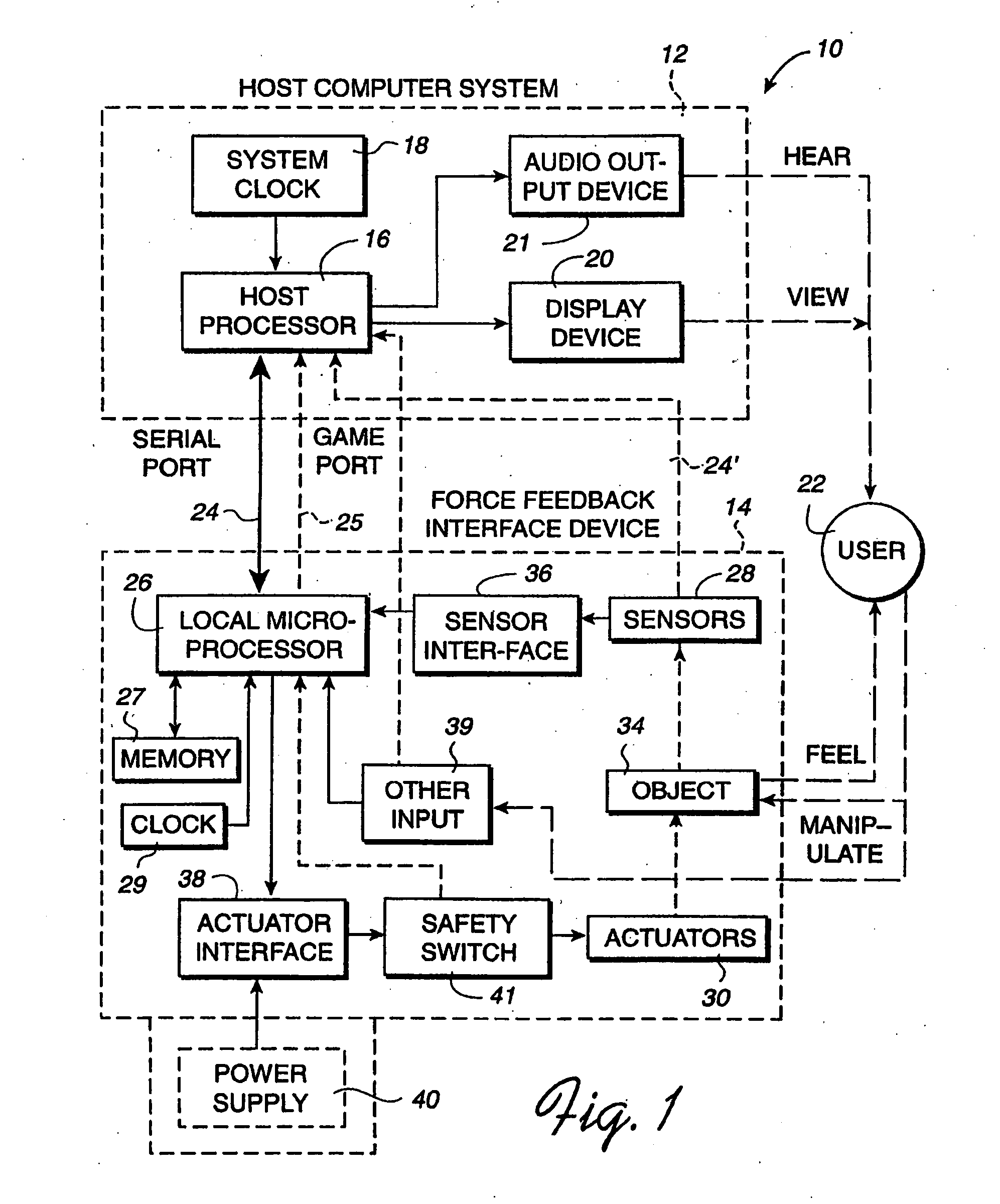
[0031]FIG. 1 is a block diagram illustrating a force feedback interface system 10 of the present invention controlled by a host computer system. Interface system 10 includes a host computer system 12 and an interface device 14.

[0032] Host computer system 12 is preferably a personal computer, such as an IBM-compatible or Macintosh personal computer, or a workstation, such as a SUN or Silicon Graphics workstation. For example, the host computer system can a personal computer which operates under the MS-DOS or Windows operating systems in conformance with an IBM PC AT standard. Alternatively, host computer system 12 can be one of a variety of home video game systems commonly connected to a television set, such as systems available from Nintendo, Sega, or Sony. In other embodiments, home computer system 12 can be a television “set top box” or a “network computer” which can be used, for example, to provide interactive computer functions to users over networks.

[0033] In the described em...


PUM


Abstract

A design interface tool for designing force sensations for use with a host computer and force feedback interface device. A force feedback device is connected to a host computer that displays the interface tool. Input from a user is received in the interface to select a type of force sensation to be commanded by a host computer and output by a force feedback interface device. Input, such as parameters, is then received from the user which designs and defines physical characteristics of the selected force sensation. A graphical representation of the characterized force sensation is displayed on the host computer which provides a visual demonstration of a feel of the characterized force sensation so that the user can view an effect of parameters on said force sensation. The characterized force sensation is output to a user manipulatable object of the force feedback device so that the user can feel the designed force sensation, where the graphical representation is updated in conjunction with the output of the force sensation. The user can iteratively modify force sensation characteristics and feel the results, and store the characterized force sensations.

Description

CROSS REFERENCE TO RELATED APPLICATIONS [0001] This application is a continuation of U.S. patent application Ser. No. 10 / 782,878, filed Feb. 23, 2004 which is a continuation of U.S. patent application Ser. No. 09 / 734,630, filed Dec. 11, 2000, on behalf of Louis B. Rosenberg et al., entitled “Designing Force Sensations For Force Feedback Computer Applications,” now U.S. Pat. No. 6,697,086, which is a continuation-in-part of parent patent application Ser. No. 08 / 566,282, filed Dec. 1, 1995, on behalf of Louis B. Rosenberg et al., entitled, “Method and Apparatus for Controlling Force Feedback Interface Systems Utilizing a Host Computer,” now U.S. Pat. No. 5,734,373 and Ser. No. 08 / 846,011, filed Apr. 25, 1997, on behalf of Rosenberg et al., entitled, “Method and Apparatus for Designing and Controlling Force Sensations in Force Feedback Computer Applications,” now U.S. Pat. No. 6,147,674 each of which assigned to the assignee of this present application, and each of which are incorporat...

Claims


Application Information

Patent Timeline
Patent Type & Authority Applications(United States)
IPC IPC(8): G09G5/00G05G9/047G06F3/00G06F3/01G06F3/038H04L29/06
CPCA63F2300/1025A63F2300/1037G05G9/047G05G2009/04766G05G2009/04777G06F3/016G06F3/03543G06F3/0383G06F2203/014G06F2203/015H01H2003/008H04L67/38H04L67/131
Inventor ROSENBERG, LOUIS B.CHANG, DEAN C.
Owner IMMERSION CORPORATION
Learn More