
Method of detecting phase-loss state of three-phase power supply

a power supply and phase loss technology, applied in emergency protective circuit arrangements, polyphase network asymmetry measurements, instruments, etc., can solve the problems of high probability of malfunction, adversely affecting the service life of rectifier b, and occupying additional space in power electronics. , to achieve the effect of reducing the cos

Active Publication Date: 2006-08-24
DELTA ELECTRONICS INC
View PDF4 Cites 24 Cited by
  • Summary
  • Abstract
  • Description
  • Claims
  • Application Information

AI Technical Summary

Benefits of technology

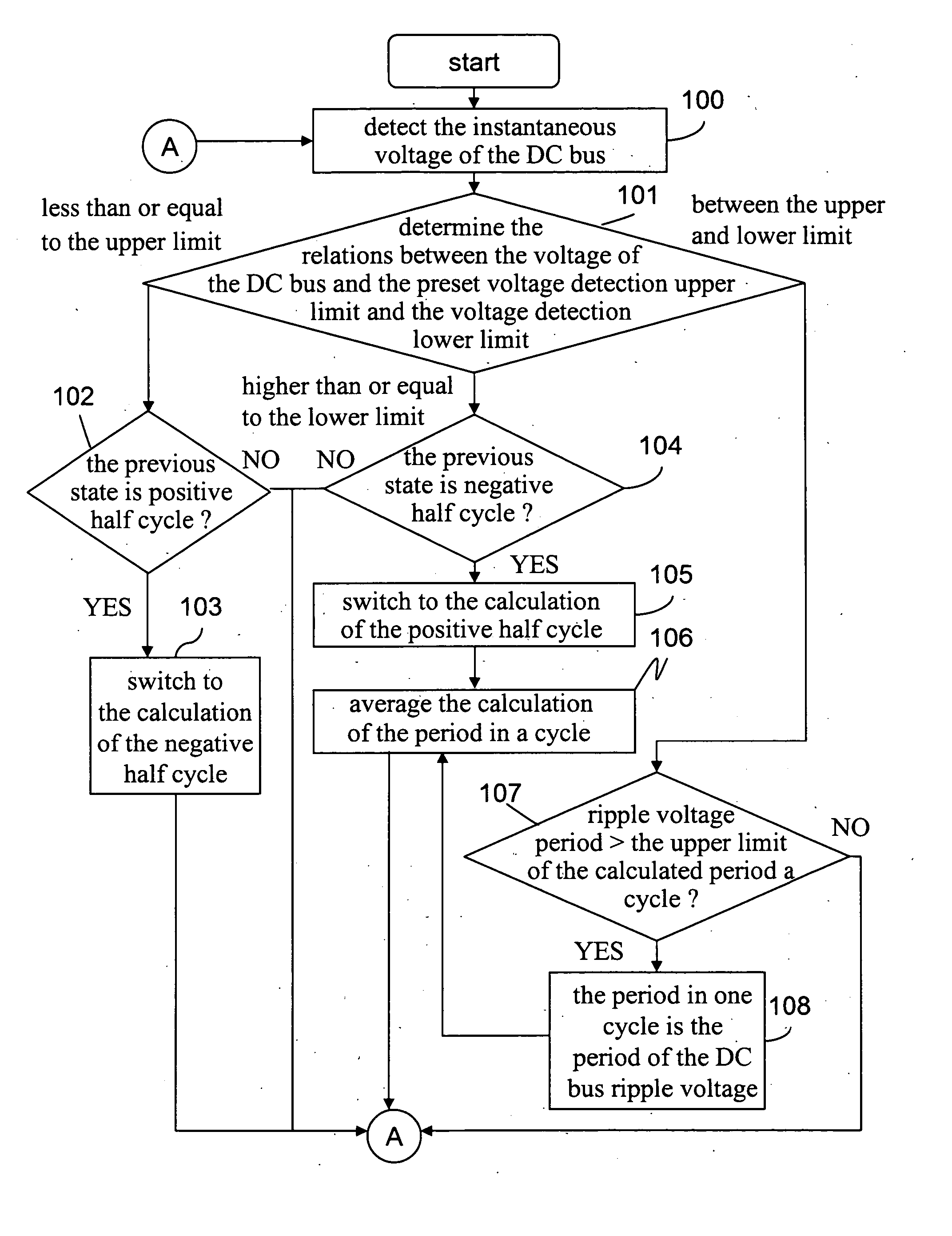
[0008] In view of the above-mentioned problems and shortcomings of the prior art, the object of the invention is to provide a method for detecting the phase-loss state of the three phase power supply, and the phase-loss state of the power source is determined through detecting the variations of the ripple voltage on the DC bus by means of software calculations instead of the hardware detection circuit as utilized in the prior art, thus achieving the objective of reducing the cost.
[0011] Through the application of the method of detecting the phase-loss state of the three-phase power source of the invention, the phase-loss state of the power source is determined through sampling and continuously detecting the variations of the ripple voltage on the DC bus by means of the software calculations instead of the hardware circuit, thus achieving the purpose of reducing the cost of the power source phase-loss detection.

Problems solved by technology

When the phase-loss condition of the three-phase power source occurs, it will result in the increase of the input current of the rectifier 10, and the augmentation of the amplitude of the ripple voltage on the DC bus, thus adversely affecting the service lives of the rectifier 10 and the capacitors in the filter circuit 20.
As such, it is liable to cause the additional cost of the hardware and the occupation of the additional space in the power electronics; besides, since the service life of an electronic component is of limited duration, its malfunction probability is pretty high.
Therefore, the research and development of a low cost power source phase-loss detection and determination method is an urgent and important task in this field.

Method used


Image

  • Method of detecting phase-loss state of three-phase power supply
  • Method of detecting phase-loss state of three-phase power supply
  • Method of detecting phase-loss state of three-phase power supply

Examples


Embodiment Construction

[0018] The purpose, construction, features, and functions of the present invention can be appreciated and understood more thoroughly through the following detailed description with reference to the attached drawings.

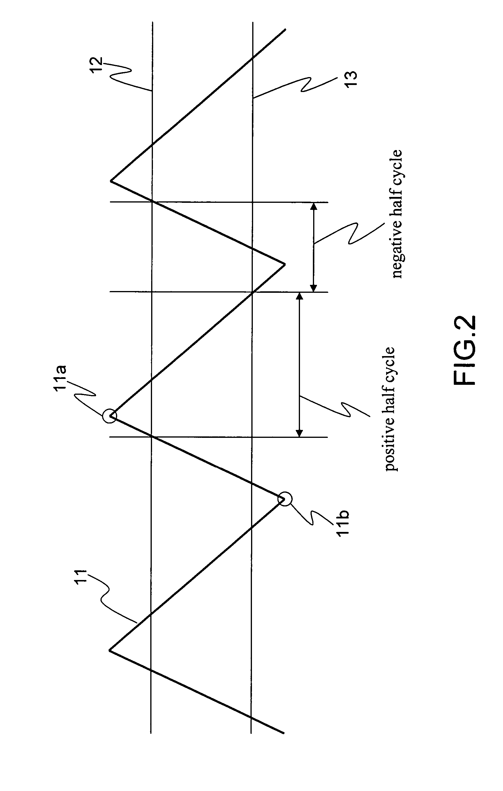
[0019] In general, the frequency of the ripple voltage of the DC bus is about 6 times the frequency of the voltage of the power source, namely, when the frequency of the voltage of the three-phase power source is 60 Hz, then the frequency of the ripple voltage of the DC bus is 360 Hz; and when the frequency of the voltage of the three-phase power source is 50 Hz, then the frequency of the ripple voltage of the DC bus is 300 Hz.

[0020] When the phase-loss state of the three-phase power source occurs, namely, it is reduced from a three-phase power source to a single phase power source, then the frequency of the ripple voltage of the DC bus is about twice the frequency of the power source voltage. For instance, when the frequency of the voltage of the single-phase power so...


PUM


Abstract

The disclosure relates to a method of detecting the phase-loss state of the three-phase power supply. When the phase-loss condition occurs in the input three-phase power supply of the power converter, it is determined whether the three-phase power source is in the phase-loss state through the characteristic of the frequency and amplitude variations of the ripple voltage of the DC bus, and through the sampling and the continuous detecting of the ripple voltage variations by making use of the sensor of the power converter in cooperation with the software calculation, it is determined whether the three-phase power source is in a phase-loss state. When the detected ripple voltage of the DC bus fulfills the phase-loss conditions, it is determined that the three-phase power source is in a phase-loss state.

Description

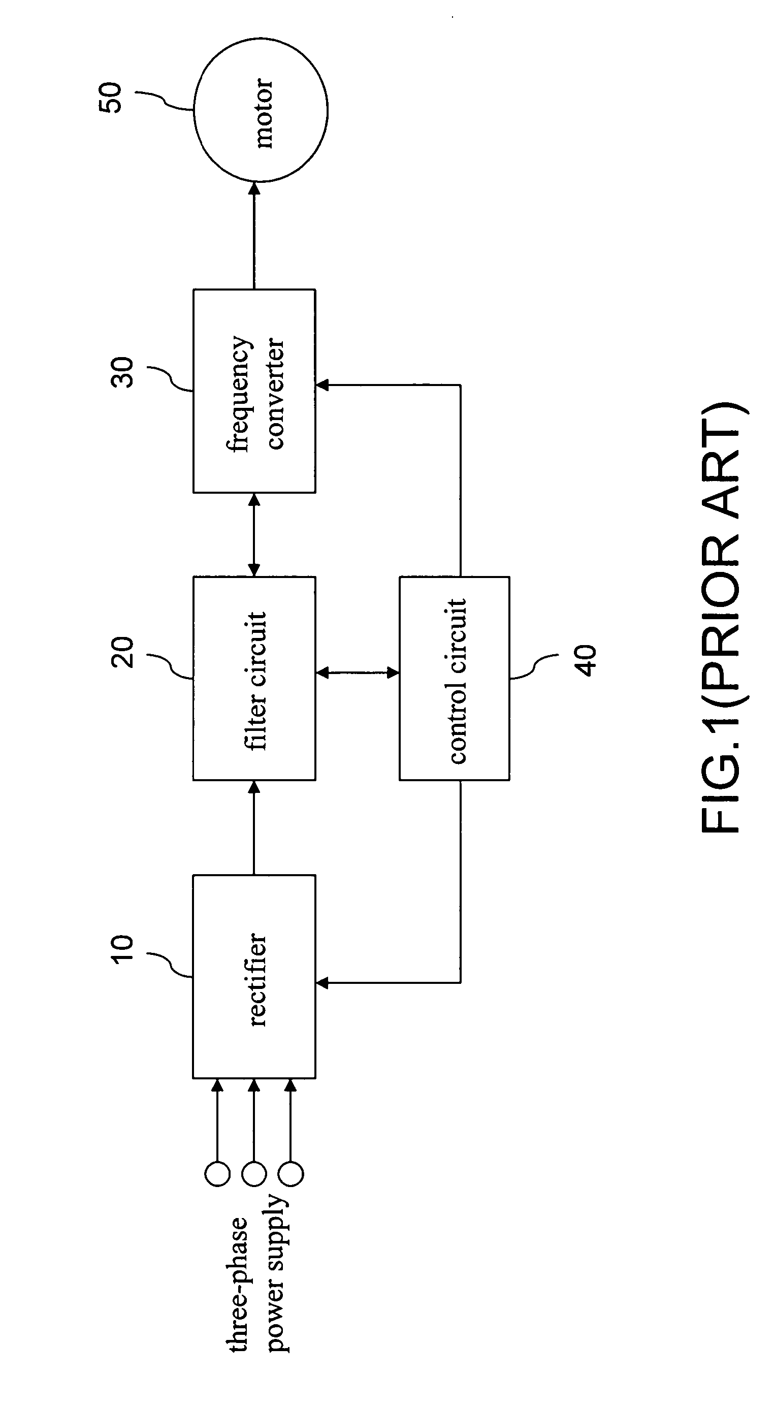
[0001] This Non-provisional application claims priority under 35 U.S.C. § 119(a) on Patent Application No(s). 094105421 filed in Taiwan on Feb. 23, 2005, the entire contents of which are hereby incorporated by reference. BACKGROUND OF THE INVENTION [0002] 1. Field of Invention [0003] The invention relates to a method of detecting the state of the power supply, and in particular to a method of detecting and determining the phase-loss state of the three-phase power supply by means of a specific software. [0004] 2. Related Art [0005] With the increasing popularity of power electronics, the application and utilization of power converters such as the Uninterruptible Power Supply system and the AC motor drive is widespread and is getting more and more prominent and important. For a comprehensive description of the prior in this respect, please refer to FIG. 1. FIG. 1 is a system block diagram of the ordinary DC-AC Inverter of the prior art. As shown in FIG. 1, the three-phase alternating ...

Claims


Application Information

Patent Timeline
IPC IPC(8): H02M5/27
CPCG01R19/16547G01R29/16H02M1/32H02M5/458
Inventor HSIEH, TING-CHUNGLIAO, SHIH-CHIEH
Owner DELTA ELECTRONICS INC
Learn More