Network system and its switches

a network system and switch technology, applied in the field of switches, can solve the problems of difficult to speed up a response, complicated processing of block access protocols such as scsi, and the processing of cache hits is complicated, so as to speed up an access to data and save network bandwidth

Inactive Publication Date: 2006-08-24
HITACHI LTD
View PDF43 Cites 186 Cited by
  • Summary
  • Abstract
  • Description
  • Claims
  • Application Information

AI Technical Summary

Benefits of technology

[0010] An object of the present invention is to speed up an access to data without changing settings of a computer in SAN so that a network bandwidth can be saved.

Problems solved by technology

In the meantime, as is the case with the transparent cache, if a network cache technology for handling data on a file basis is used, it is difficult to speed up a response because processing for judging a cache hit is complicated.
Because this search processing judges the coincidence of a name or the like, processing of the block access protocol such as SCSI becomes more complicated than the comparison between numerical values of logical block addresses used to specify locations to be accessed.

Method used


Image

  • Network system and its switches
  • Network system and its switches
  • Network system and its switches

Examples


first embodiment

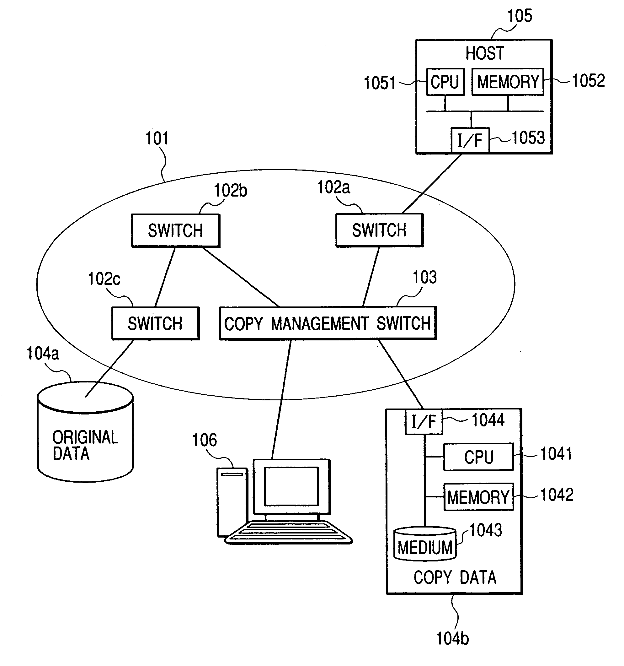
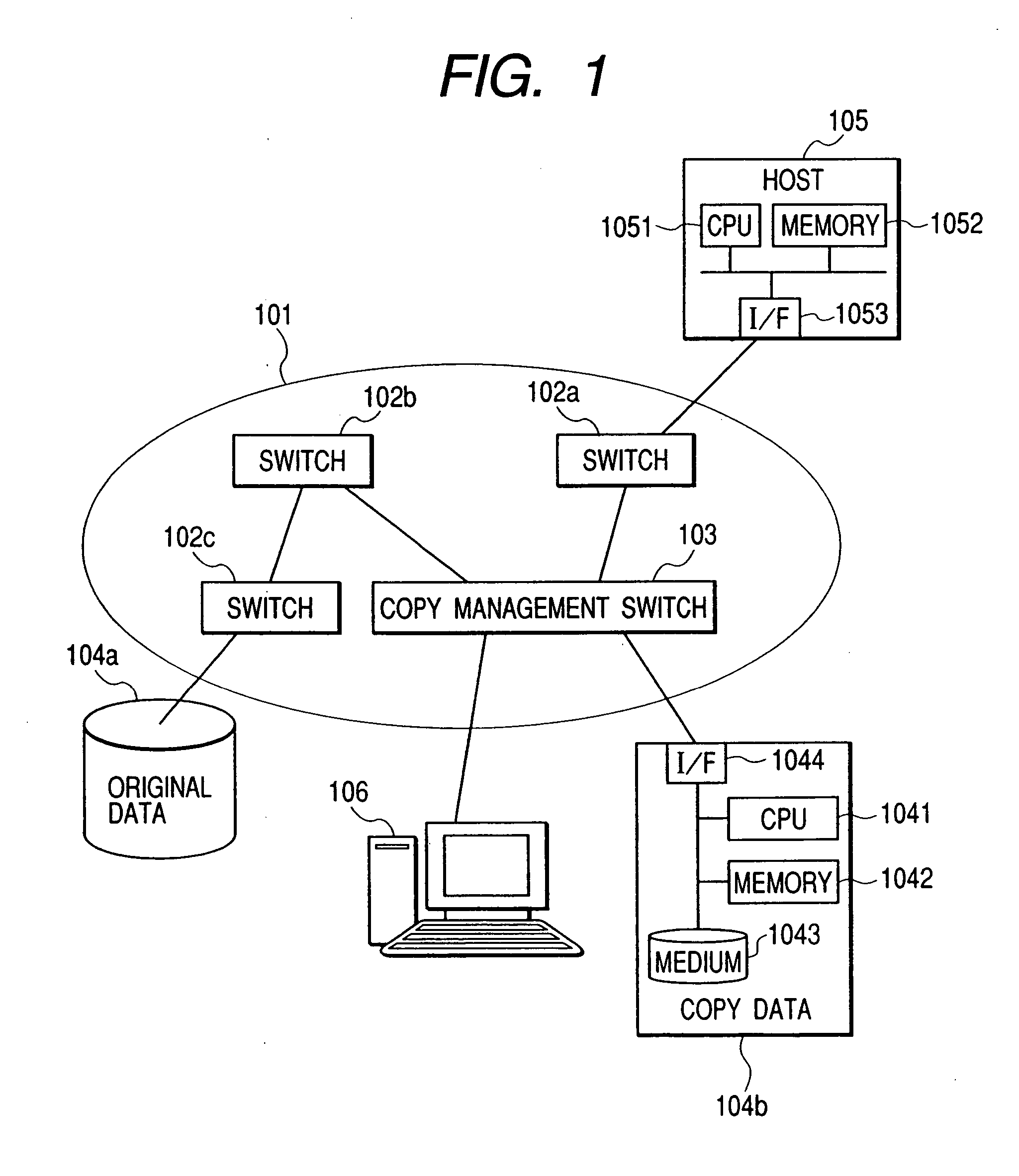
[0036]FIG. 1 is a diagram illustrating a computer system to which the present invention is applied. The computer system comprises a SAN 101, a host 105, a storage device 104a, and a storage device 104b. The host 105, the storage device 104a, and the storage device 104b are interconnected over the SAN 101. The SAN 101 comprises the host 105, switches 102a, 102b, 102c, and a copy management switch 103 described later.

[0037] This embodiment, which will be described below, is based on the assumption that the host 105 makes a read request for data (hereinafter referred to as “original data”) stored in the storage device 104a.

[0038] The host 105 is a computer comprising a CPU 1051, a memory 1052, and an interface 1053 used to make a connection to the SAN 101.

[0039] The storage device 104 comprises the following: a medium 1043 for storing data; an interface 1044 used to make a connection to the SAN 101; a CPU 1041 for executing a program used to respond to a request from the host 105; an...

third embodiment

[0119]FIG. 9 is a diagram illustrating a configuration example of a computer system to which a third embodiment according to the present invention is applied. A SAN 101 comprises switches 102a, 102b and a copy management switch 303. In addition, a host 105, a storage device 104a, and a storage device 104b are connected to the SAN 101. Original data is stored in the storage device 104a.

[0120] It should be noted that this embodiment also based on the assumption that a connection cost for a communication line between the host 105 and the storage device 104a is higher than that for a communication line between the host 105 and the storage device 104b.

[0121] As is the case with the other embodiments described above, the user, or the administrator, of the system uses the management terminal 106, which is connected to the copy management switch 303, to copy original data, and then to write information about the association of the original data with the copy data to the copy management ta...

second embodiment

[0125] A first point of difference is that the CPU 1121 executes an initialization program 321 (the initialization program 121 used for the copy management switch 303) to read the virtual address table 341 described below from the non-volatile storage 1123, and then to write to the name database 125 the address information of the virtual storage 307 stored in the virtual address table 341. A second point of difference is that the CPU 1121 executes a management-terminal-submitted request processing program 322 (the request processing program 122 used for the copy management switch 303) not only to perform the processing in the second embodiment, but also to change the virtual address table 341 held in the non-volatile storage 1123 in response to a request that comes from the management terminal 106 and is received by the management port 113.

[0126]FIG. 10 is a diagram illustrating contents of the virtual address table 341. The virtual address table 341 comprises a plurality of virtual...


PUM


Abstract

A copy management switch is placed in a network that connects a storage device with a computer. This copy management switch is connected to the computer, a first storage device, and a second storage device over the network. The copy management switch copies beforehand data stored in the first storage device to the second storage device. On receiving a read request, which is issued from the computer to the first storage device, the copy management switch converts the read request to the first storage device into a read request to the second storage device, and then transmits the converted read request to the second storage device. The second storage device transfers, to the copy management switch, data corresponding to the read request. The copy management switch transfers the data to the computer as data transferred from the first storage device.

Description

BACKGROUND OF THE INVENTION [0001] The present invention relates to switches placed in a network that connects a storage device with a computer. [0002] With the increasing storage capacity of storage devices used in companies and the like, a system in which a connection between storage devices, or between storage devices and computers, is made via a network such as a fiber channel is becoming popular. The network providing a connection between the storage devices or between others, or the total system in which a connection is made via the network, is called a storage area network (hereinafter referred to as SAN). [0003] On the other hand, examples of technologies that reduce the frequency of data transfer in a network so as to shorten time required for causing a computer to access data stored in a storage device include a network cache technology. To be more specific, a storage area (hereinafter referred to as a “cache device”) for temporarily storing data on a network is first prep...

Claims


Application Information

Patent Timeline
Patent Type & Authority Applications(United States)
IPC IPC(8): H04L12/50G06F13/00G06F12/00G06F17/30H04L12/28H04L29/06
CPCG06F17/30197G06F16/1824
Inventor SHIMOZONO, NORIOIWAMI, NAOKOHONDA, KIYOSHI
Owner HITACHI LTD
Why Eureka
Try Eureka