Adjustable support bracket for concrete reinforcing bars

a technology of reinforcement bar and support bracket, which is applied in the direction of paving reinforcements, auxiliaries of forms/shuttering/falseworks, and ways, etc., can solve the problems of weakened concrete structure lacking the ability to properly dissipate forces, requiring additional labor and some degree of skill within the form, and requiring expensive time and labor. , to achieve the effect of simple and cost-effectiv

Inactive Publication Date: 2006-08-24
HUBER DONALD G
View PDF8 Cites 22 Cited by
  • Summary
  • Abstract
  • Description
  • Claims
  • Application Information

AI Technical Summary

Benefits of technology

[0012] It is an object of the present invention to provide a simple and cost-effective apparatus for supporting concrete reinforcing bars that offers an improved alternative to wiring reinforcing bars into position within a reinforced concrete structure.

Problems solved by technology

However, haphazard positioning of the reinforcing bars would result in a weakened concrete structure lacking in the ability to properly dissipate forces.
Placing the reinforcing bar securing devices in the desired location within the form requires additional labor and some degree of skill.
While this practice is cost-effective from a materials standpoint, it is expensive in terms of the time and labor required.
While these devices offer a cost-saving alternative in the construction of concrete forms, a problem remains when a construction project requires forms of different thicknesses.
Additional time would be required to have these devices modified for different wall thickness, or additional expense would be involved in maintaining an inventory of various length brackets for a particular project.

Method used


Image

  • Adjustable support bracket for concrete reinforcing bars
  • Adjustable support bracket for concrete reinforcing bars
  • Adjustable support bracket for concrete reinforcing bars

Examples


second embodiment

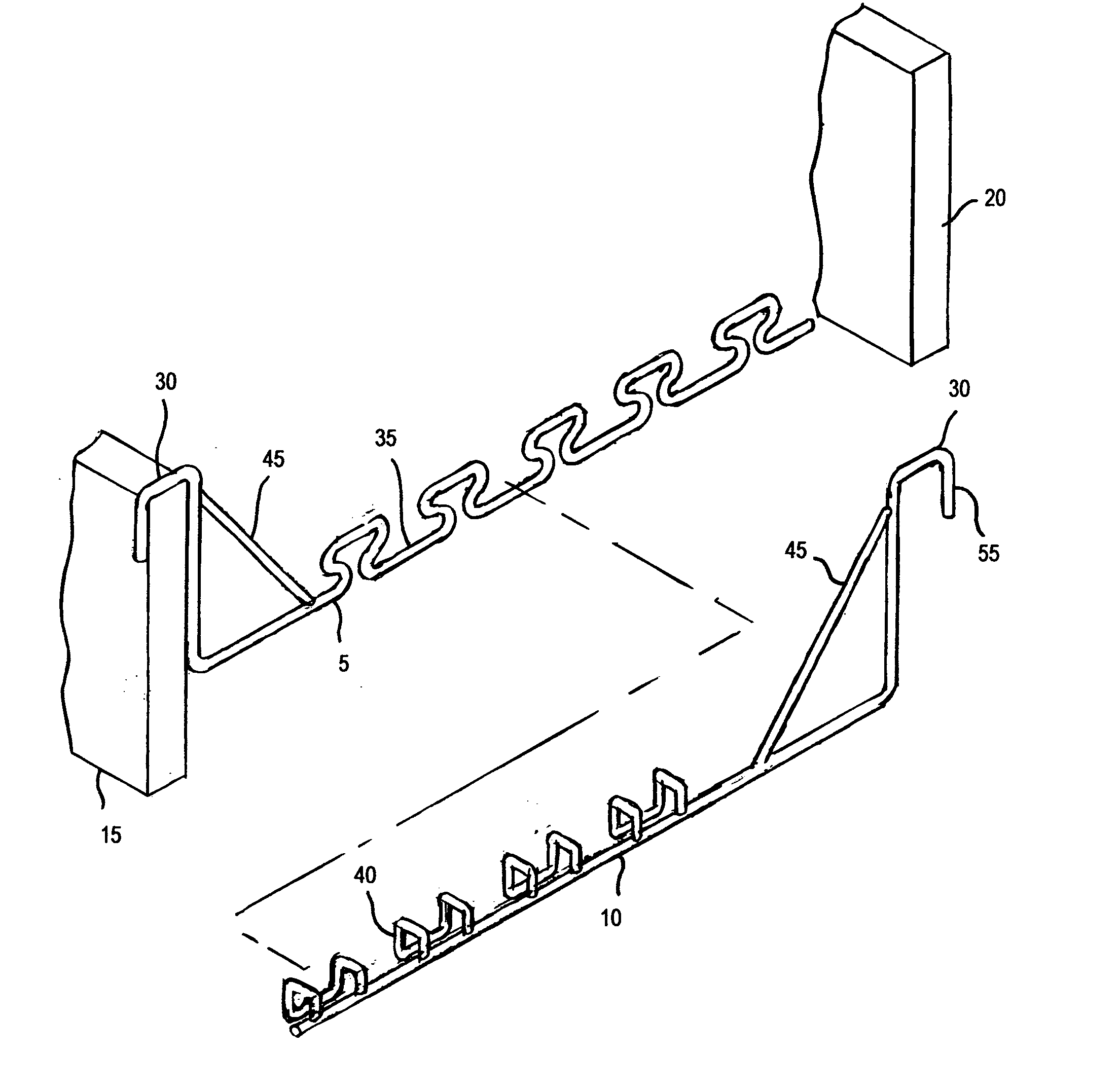
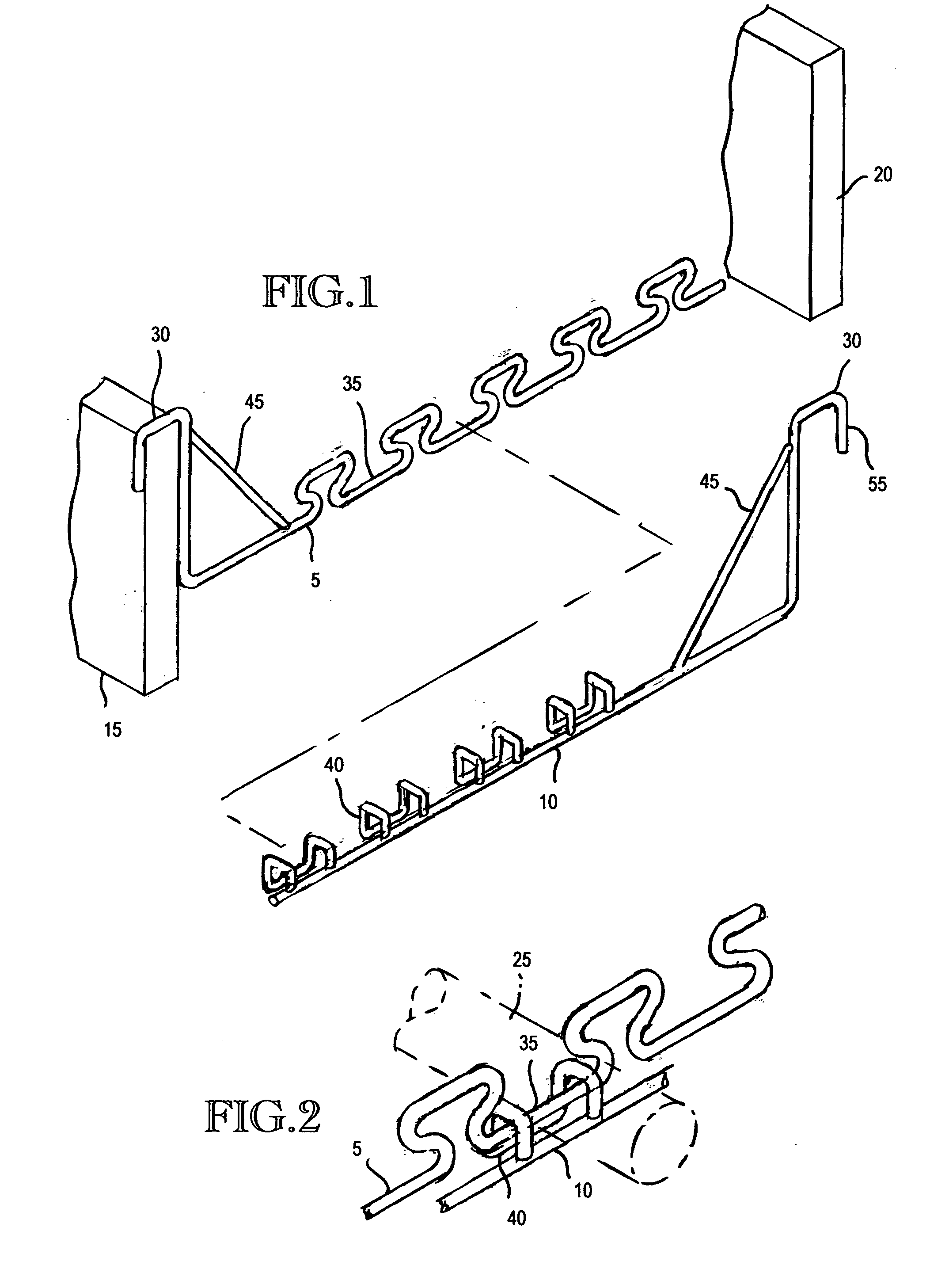
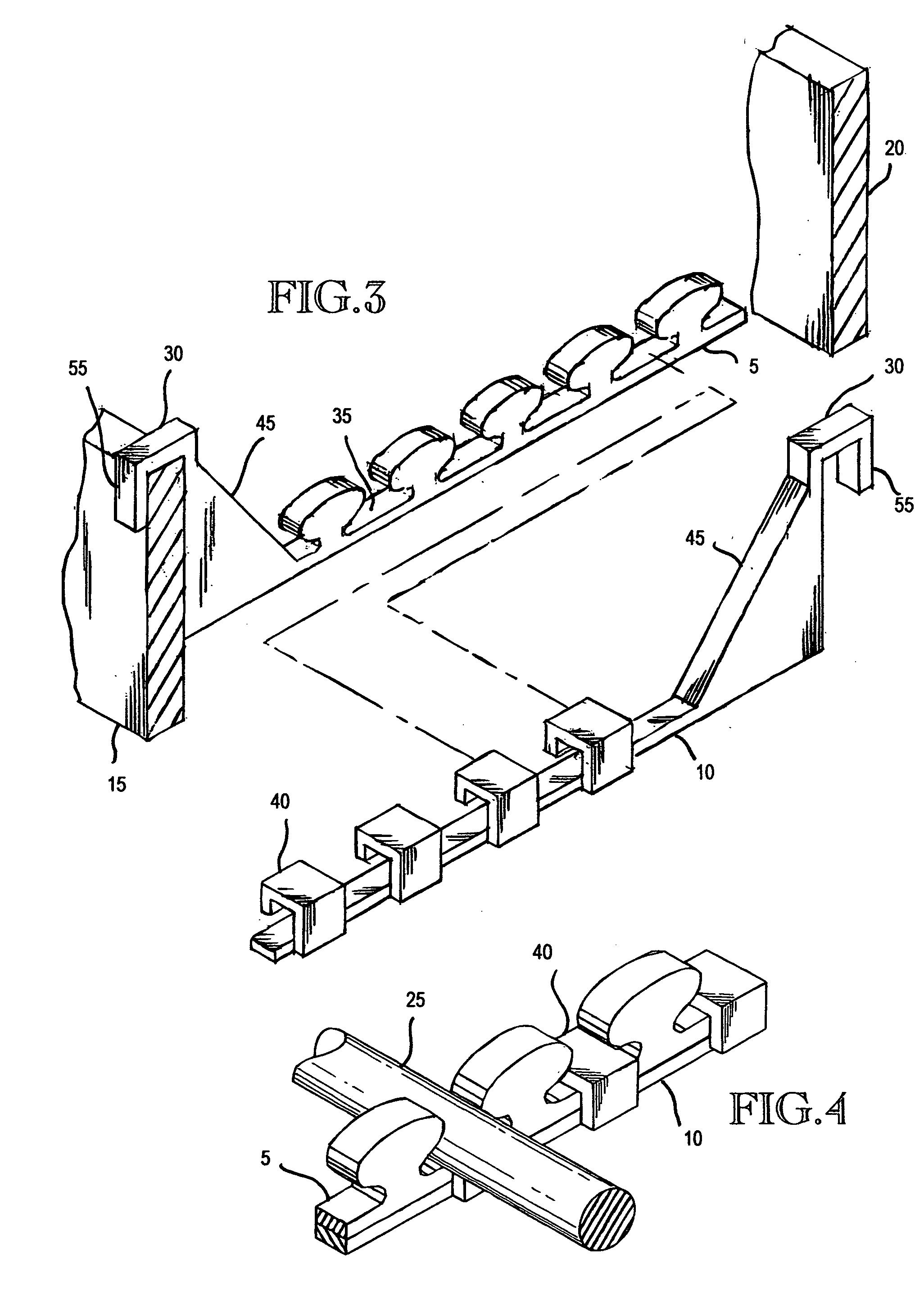
[0039] the present invention is shown in FIG. 2. In this embodiment the first member 5 and second member 10 are also formed of medium steel wire that is bent to form the recessions 35 and longitudinally disposed projections 40. The projections 40 are angled or curved toward the corresponding recessions 35 such that the first member 5 and the second member 10 can be overlapped to engage each other at any one of a plurality of locations along a common longitudinal axis. The first member 5 is further comprised of a plurality of apertures 70, and the second member 10 is further comprised of a plurality of secondary longitudinally disposed projections 75 that are angled or curved toward the corresponding apertures 70, whereby the first member 5 and the second member 10 are simply aligned on a common longitudinal axis, overlapping to form a desired length of the bracket assembly 1, and are rotated to engage and interlock the recessions 35 and projections 40, as shown in detail in FIG. 3, ...

third embodiment

[0040] the present invention is shown in FIG. 5. Each of the first member 5 and the second member 10 is formed of a ribbon-like medium steel strip stock that is bent to form the recessions 35 and longitudinally disposed projections 40. Each member may be of a continuous length of wire or may be built up of a plurality of pieces boned or welded together. The size and shape of the second member 10 is such that the second member 10 nests within the first member 5, whereby a desired length of the adjustable bracket assembly 1 is achieved by positioning the two members to align corresponding recessions 35 and projections 40, and laterally engaging and sliding the two members together.

fourth embodiment

[0041] In a fourth embodiment as shown in FIG. 6, an adjustable bracket is comprised a first member 5 and a second member 10, each of which has a plurality of recessions 35 for receiving a plurality of reinforcement bars 25. The first member 5 is supportable from a first form wall 15 and the second member 10 is supportable by a second opposing form wall 20. A forward-facing surface on the first member 5 has a plurality of fasteners 85 such as snaps, clips or retaining tabs positioned along the length of the first member 5 as shown in FIG. 7. The second member 10 has a rearward-facing surface with a corresponding plurality of fasteners 85 positioned thereon, as seen in detail in FIG. 8, such that the length of the bracket assembly 1 is adjustable by overlapping the first member 5 with the second member 10 to achieve a desired length, aligning the recessions 35 of each member, and engaging and snapping the fasteners 85 together. This embodiment is preferably made of steel strip stock ...


PUM


Abstract

An adjustable bracket is provided for supporting concrete reinforcing bars for use in the construction of concrete structures. In particular, The present invention is an apparatus, system and method for supporting concrete reinforcing bars as used in the construction of concrete structures. In particular, this invention relates to an adjustable support for reinforcement bar, or similar reinforcing members, a plurality of which are disposed within a concrete form. The support is adjustable to a desired length corresponding to the cross-sectional width of the form. The support is mounted across opposing form walls providing a simple, inexpensive and time-saving means of positioning reinforcing bars in an essentially parallel arrangement within the form prior to the form's being filled with liquified concrete. In one embodiment of the present invention, and adjustable support is disclosed having an assembly of interlocking members with one member supportable by one form wall and having multiple holes for reinforcement bar, and another member supportable by an opposing form wall and having multiple retainer segments aligned with the reinforcement bar holes of the first member, whereby the two members are axially positionable and lockable to a desired length of bracket to support transversely mounted reinforcing bars. In an alternate embodiment, an adjustable bracket is formed of two molded members, each of which has multiple holes for reinforcement bar, the first member being supportable from a first by wall and the second member being supportable by an opposing wall, whereby each member is overlapped with the other to be axially positionable and lockable to a desired length of bracket. In another embodiment, an adjustable bracket is formed of two molded members, the first member of which is supportable by one form wall and has multiple holes for reinforcement bar and score marks at regular intervals to allow a worker to selectively and easily break off an undesired excess length of material. The second member is supportable by an opposing form wall and has a recess to receive the broken-off end of the first member, whereby the two members are axially positionable to a desired length of bracket.

Description

CROSS-REFERENCE TO RELATED APPLICATION [0001] This application claims priority to U.S. Provisional Patent Application No. 60 / 645,911, entitled “ADJUSTABLE SUPPORT BRACKET FOR CONCRETE REINFORCING BARS,” filed Feb. 23, 2005.TECHNICAL FIELD [0002] The invention relates to brackets for supporting concrete reinforcing rods as used in the construction of concrete structures. In particular, this invention relates to an adjustable support bracket for reinforcement bar, or similar reinforcing members, a plurality of which are disposed within a concrete form. The support is adjustable to a desired length corresponding to the cross-sectional width of the form. The support is mounted across opposing form walls providing a simple, inexpensive and time-saving means for positioning pieces of reinforcement bar in an essentially parallel arrangement within the form prior to the form's being filled with liquified concrete. BACKGROUND OF THE INVENTION [0003] In the art of building construction it is ...

Claims


Application Information

Patent Timeline
Patent Type & Authority Applications(United States)
IPC IPC(8): E01C11/18
CPCE04C5/168E04C5/205E04G17/12
Inventor HUBER, DONALD G.
Owner HUBER DONALD G
Why Eureka
Try Eureka