Furnace and process for drawing radiation resistant optical fiber

a radiation resistance and optical fiber technology, applied in the field of optical fibers, can solve the problems of radiation resistance, radiation resistance, and improper fiber draw conditions, and achieve the effects of reducing radiation resistance, reducing radiation resistance, and reducing radiation resistan

Inactive Publication Date: 2006-08-31
WEATHERFORDLAMB
View PDF5 Cites 69 Cited by
  • Summary
  • Abstract
  • Description
  • Claims
  • Application Information

AI Technical Summary

Problems solved by technology

Standard telecommunications optical fibers are highly susceptible to optical signal losses caused by nuclear or ionizing radiation.
Improper fiber draw conditions can be detrimental to radiation resistance.
While this phenomena is not completely understood, it is believed that non-optimized draw conditions cause internal stress within the waveguide.
Radiation can rupture these strained bonds causing defect sites within the glass leading to increased optical signal attenuation.

Method used


Image

  • Furnace and process for drawing radiation resistant optical fiber
  • Furnace and process for drawing radiation resistant optical fiber
  • Furnace and process for drawing radiation resistant optical fiber

Examples


Embodiment Construction

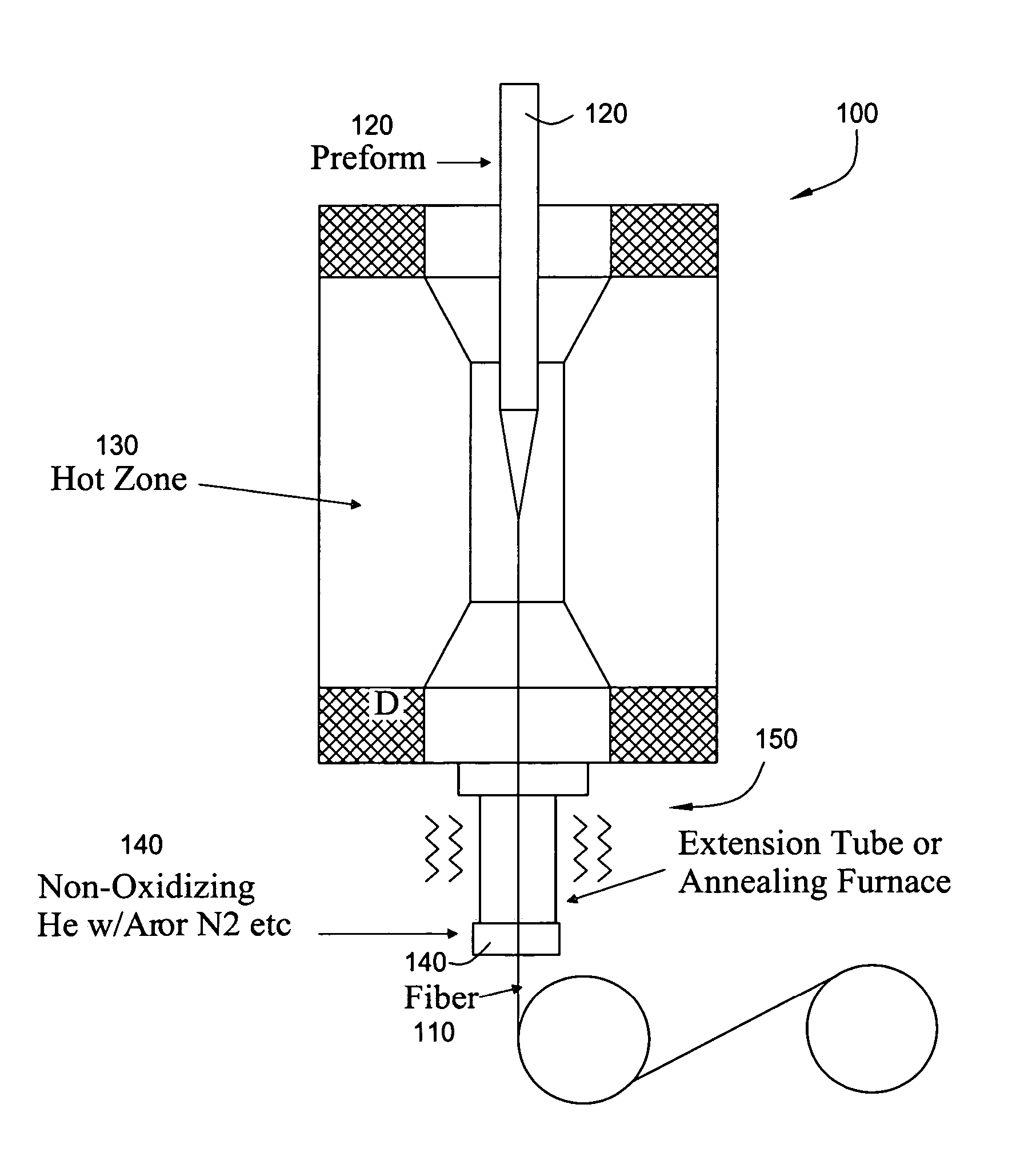
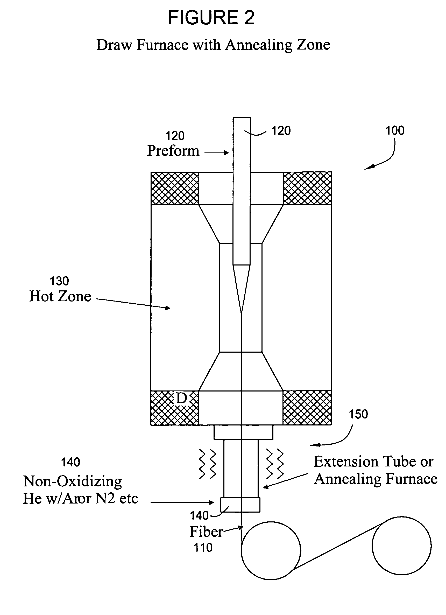
[0016] Embodiments of the present invention provide various apparatus and methods to fabricate a radiation hardened optical fiber from a preform. Various parameters affecting the draw process are controlled to optimize the radiation resistance of the resulting fiber. In some cases an annealing zone may be provided at the bottom of a draw furnace, allowing a drawn optical fiber to undergo an annealing process after exiting a primary hot zone. This annealing process may relax internal stresses and increase radiation resistance of the drawn fiber.

As Exemplary Draw Furnace

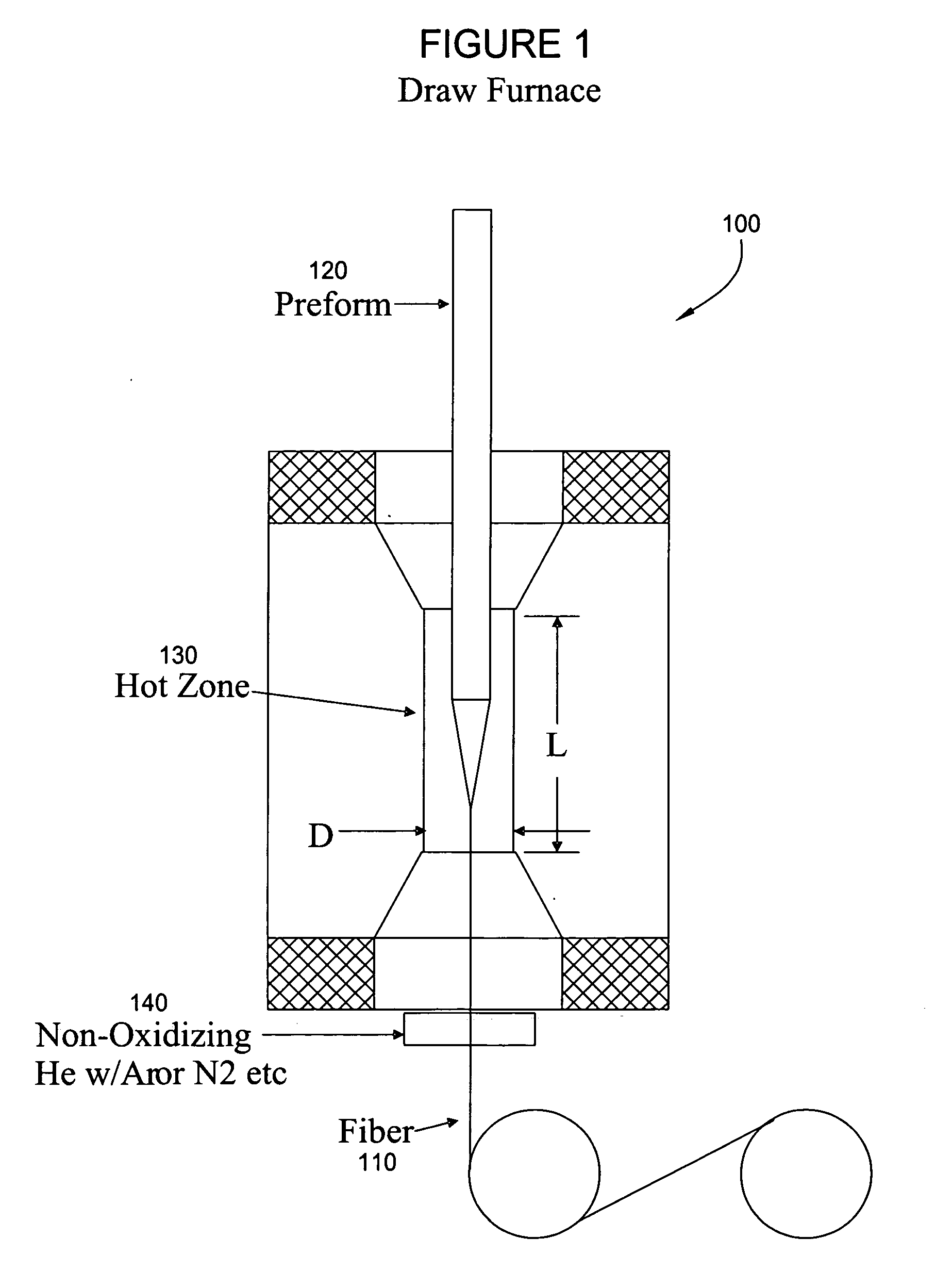
[0017]FIG. 1 illustrates an exemplary draw furnace in accordance with embodiments of the present invention that may be used to draw a radiation hardened fiber 110 from a preform 120. As illustrated, the preform 120 is fed into the furnace and enters a hot zone 130, where the preform softens and begins to melt. Below (e.g., at the bottom of a draw tower), the fiber 110 may be pulled and wound onto spools.

[0018] For s...


PUM

PropertyMeasurementUnit
lengthaaaaaaaaaa
temperatureaaaaaaaaaa
optical signal lossesaaaaaaaaaa

Abstract

Apparatus and methods to fabricate a radiation hardened optical fiber from a preform are provided. Various parameters affecting the draw process are controlled to optimize the radiation resistance of the resulting fiber. An annealing zone may be provided to allow a drawn fiber exiting a primary hot zone to undergo an annealing process which may increase radiation resistance.

Description

CROSS-REFERENCE TO RELATED APPLICATIONS [0001] This application claims benefit of U.S. Provisional patent application Ser. No. 60 / 657,161 filed Feb. 28, 2005, which is incorporated herein by reference.BACKGROUND OF THE INVENTION [0002] 1. Field of the Invention [0003] Embodiments of the present invention generally relate to optical fibers and, more particularly, to a furnace and process for drawing optical fibers from a preform. [0004] 2. Description of the Related Art [0005] Optical fibers and other type waveguides are typically formed by heating and drawing an optical fiber preform. The preform typically includes a core and surrounding cladding, with appropriate dopants to achieve desired characteristics of the resulting drawn fiber. [0006] Standard telecommunications optical fibers are highly susceptible to optical signal losses caused by nuclear or ionizing radiation. Careful selection of dopants and process conditions during glass fabrication have been shown to improve radiatio...

Claims


Application Information

Patent Timeline
Patent Type & Authority Applications(United States)
IPC IPC(8): C03B37/07C03B25/10C03B37/027F27B1/26
CPCC03B37/02727C03B37/029C03B2205/56
Inventor KUCZMA, ANDREW S.
Owner WEATHERFORDLAMB
Why Eureka
Try Eureka