Ultrasonic probe

Inactive Publication Date: 2006-08-31
KONICA MINOLTA INC
View PDF8 Cites 9 Cited by
  • Summary
  • Abstract
  • Description
  • Claims
  • Application Information

AI Technical Summary

Benefits of technology

[0005] The present invention has been made to solve the above-mentioned conventional problems, and its

Problems solved by technology

However, when a great mechanical shock is applied externally to such a conventional ultrasonic probe due to, for example, dropping or damage caused by careless handling or the like, the shock is transmitted to the inside of the storage portion, so that the ultrasonic element and the rotating mec

Method used


Image

  • Ultrasonic probe
  • Ultrasonic probe
  • Ultrasonic probe

Examples


Embodiment Construction

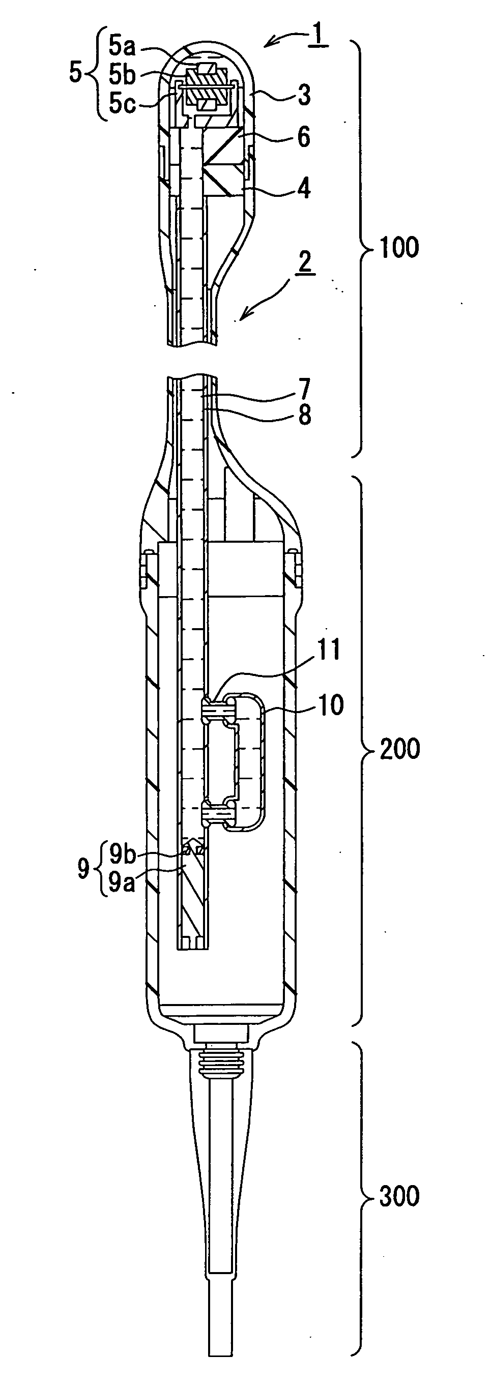
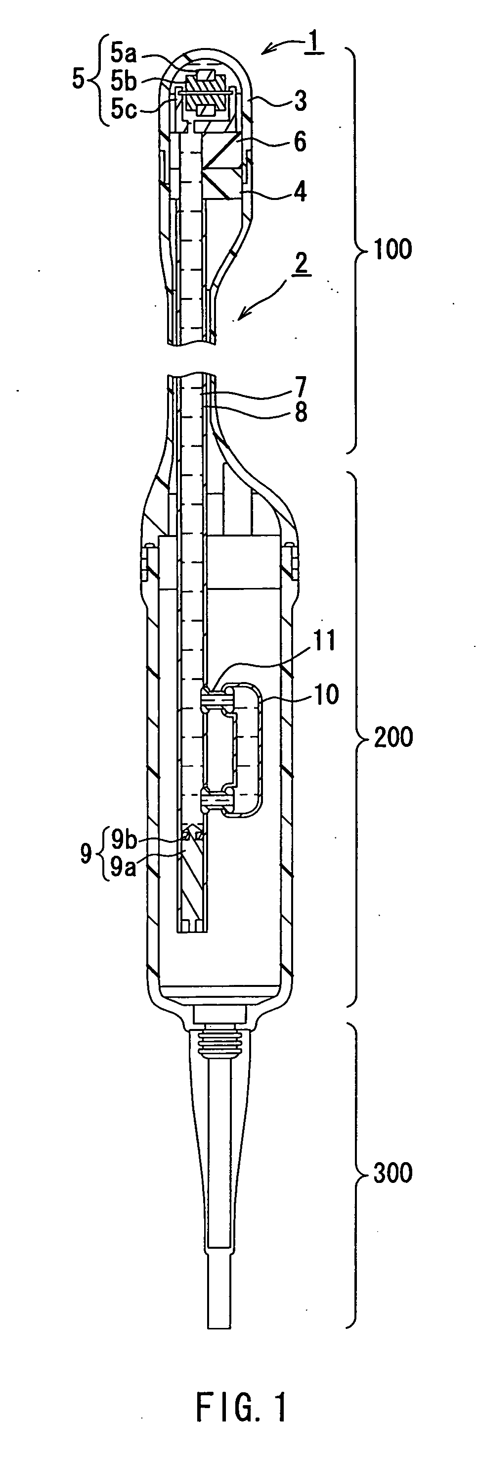
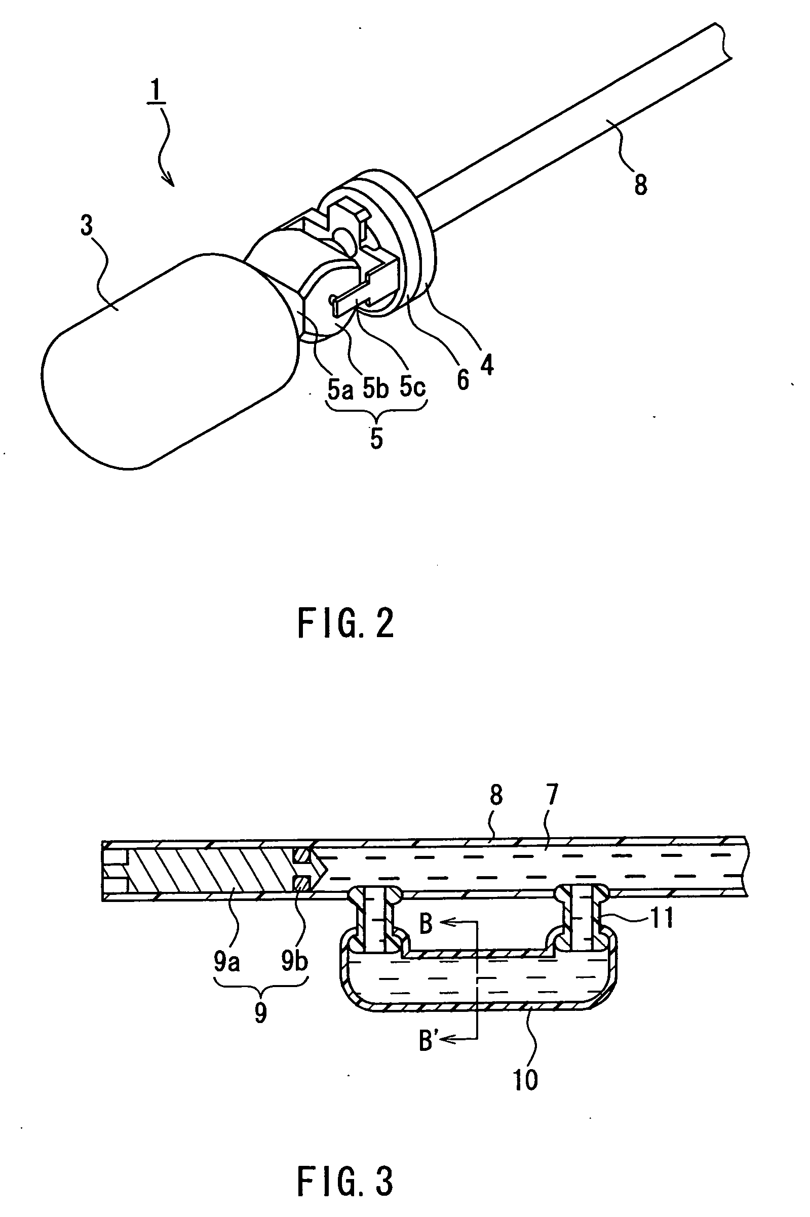
[0012] As described above, in the ultrasonic probe according to the present invention, the ultrasonic element unit is supported by an elastic supporting member, and the supporting member seals the storage portion for storing the ultrasonic element unit and the acoustic medium liquid in a liquid-tight state.

[0013] According to the above ultrasonic probe, the ultrasonic element unit is supported by the elastic supporting member in the storage portion. Therefore, even when an external shock is applied to the probe, the supporting member absorbs the shock so as to relieve stress to be applied to the ultrasonic element unit.

[0014] Further, the supporting member also serves as a sealing member for sealing the storage portion in a liquid-tight state with its elasticity. Therefore, with the sealing function of the supporting member, even when an external shock is applied to the probe, it is possible to suppress the entry of air bubbles that occurs when the liquid-tight state in the storag...


PUM


Abstract

An ultrasonic probe according to the present invention includes: an ultrasonic element unit for transmitting and receiving an ultrasonic wave while carrying out ultrasonic scanning; a storage portion for storing the ultrasonic element unit; and an acoustic medium liquid charged in the storage portion. The ultrasonic element unit is supported by an elastic supporting member, and the storage portion is sealed by the supporting member in a liquid-tight state.

Description

TECHNICAL FIELD [0001] The present invention relates to an ultrasonic probe, and more specifically to an ultrasonic probe with excellent resistance to an external shock. BACKGROUND ART [0002] A known ultrasonic probe for use in ultrasonic diagnostic apparatuses includes an ultrasonic element that is rotated in a storage portion filled with an acoustic coupling medium having an acoustic impedance similar to that of a living body, thereby transmitting and receiving ultrasonic waves. In such an ultrasonic probe, the ultrasonic element and a rotating mechanism portion for rotating the same are arranged in the storage portion, and these elements are fixed to a housing or a frame constituting the storage portion by fastening with screws, adhesive bonding with an adhesive, or the like (for example, JP 2001-327499 A). [0003] However, when a great mechanical shock is applied externally to such a conventional ultrasonic probe due to, for example, dropping or damage caused by careless handling...

Claims


Application Information

Patent Timeline
IPC IPC(8): G01H11/00A61B8/12G10K11/02
CPCA61B8/12A61B8/445G10K11/02A61B8/4461
Inventor HASEGAWA, SHIGEYOSHIFUJII, KIYOSHISAKAGAITO, YUKUO
Owner KONICA MINOLTA INC
Why Eureka
Try Eureka