
Hermetic type compressor with wave-suppressing member in the oil reservoir

a technology of oil reservoir and compression member, which is applied in the direction of machines/engines, liquid fuel engines, positive displacement liquid engines, etc., can solve the problems of deteriorating compressor efficiency, insufficient sealing of compression mechanism, and deteriorating reliability, so as to prevent the rippage of the interface and reduce the amount of oil to be discharged

Inactive Publication Date: 2006-08-31
PANASONIC CORP
View PDF10 Cites 8 Cited by
  • Summary
  • Abstract
  • Description
  • Claims
  • Application Information

AI Technical Summary

Benefits of technology

[0032] With this aspect, since the wave-suppressing member is located in the interface, the rippling of the interface caused by the turning flow is reliably prevented. Thus, the oil drops torn from the interface by the turning flow is reduced, and the oil drops of the refrigeration oil are prevented from being supplied from the interface to the working fluid. That is, the amount of refrigeration oil to be taken out from the container is reduced, and efficient refrigeration cycle can be obtained.
[0056] With this aspect, ripple of the interface is prevented and the amount of oil to be discharged can be reduced. Therefore, carbon dioxide as environmentally friendly refrigerant can be used.

Problems solved by technology

However, in the case of a compressor in which a large amount of refrigeration oil is discharged, since the oil level of the refrigeration oil in the oil reservoir 21 is lowered, the supply oil amount becomes insufficient, and the lubrication of the compression mechanism becomes insufficient, the reliability is deteriorated, the sealing of the compression mechanism becomes insufficient, and the efficiency of the compressor is deteriorated.
Thus, the performance of the refrigeration cycle is deteriorated.
The oil drops supplied from the interface 24 to the working fluid increases the amount of oil drops included in the working fluid, and it becomes difficult to separate the oil drops from the working fluid.
In this case, however, there is a problem the compressor is increased in size.
Irrespective of a difference between the vertical type and the lateral type or irrespective of a difference of the compressing manners, if the main flow working fluid passes in the vicinity of an end surface of the rotor and form a turning flow and the turning flow affects the interface while working fluid discharged from the compression mechanism is discharged from the discharge pipe provided on the container, the same problem is caused.
Therefore, there is a problem that it becomes more difficult to separate the oil using gravity or centrifugal force.

Method used


Image

  • Hermetic type compressor with wave-suppressing member in the oil reservoir
  • Hermetic type compressor with wave-suppressing member in the oil reservoir
  • Hermetic type compressor with wave-suppressing member in the oil reservoir

Examples


first embodiment

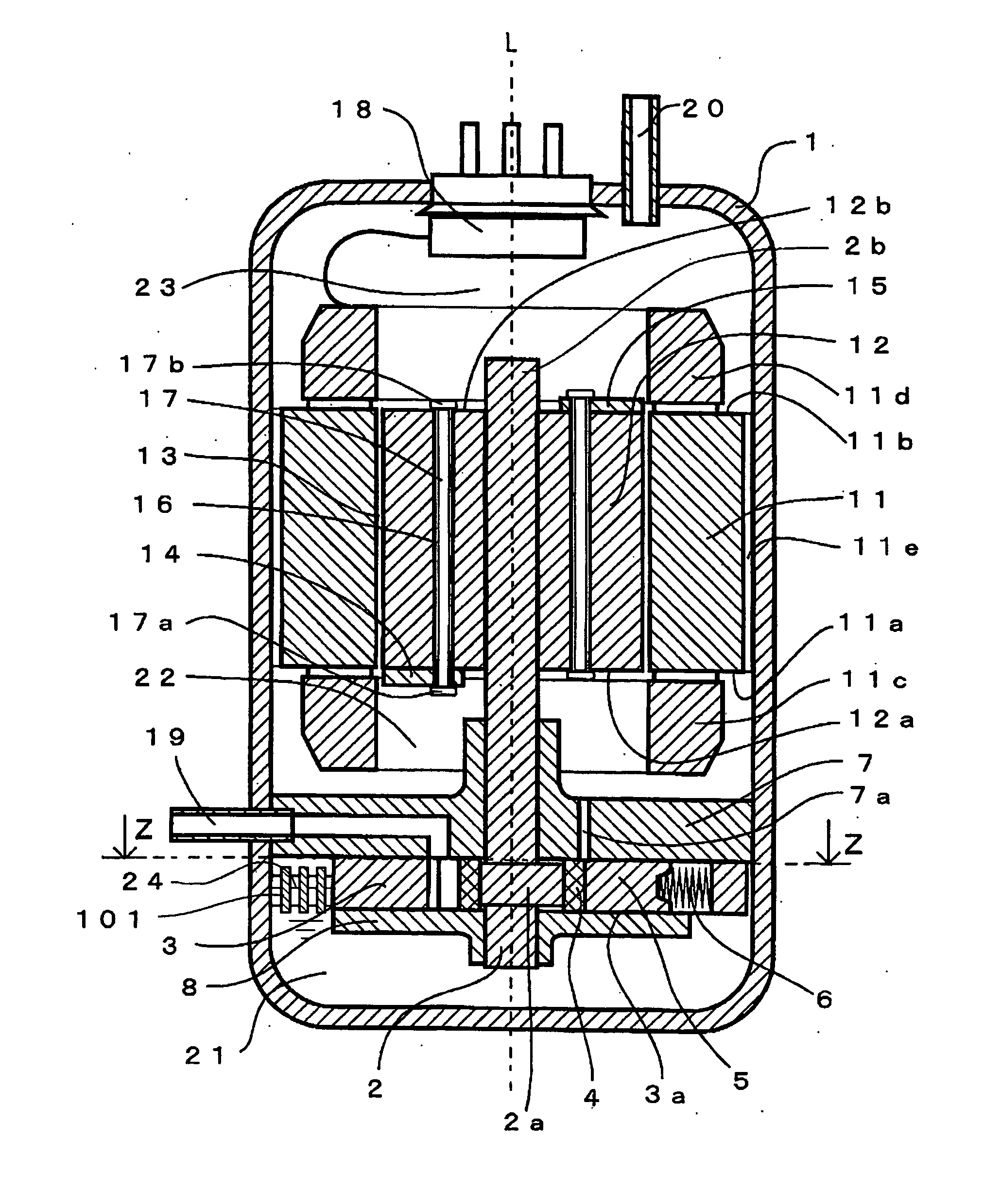
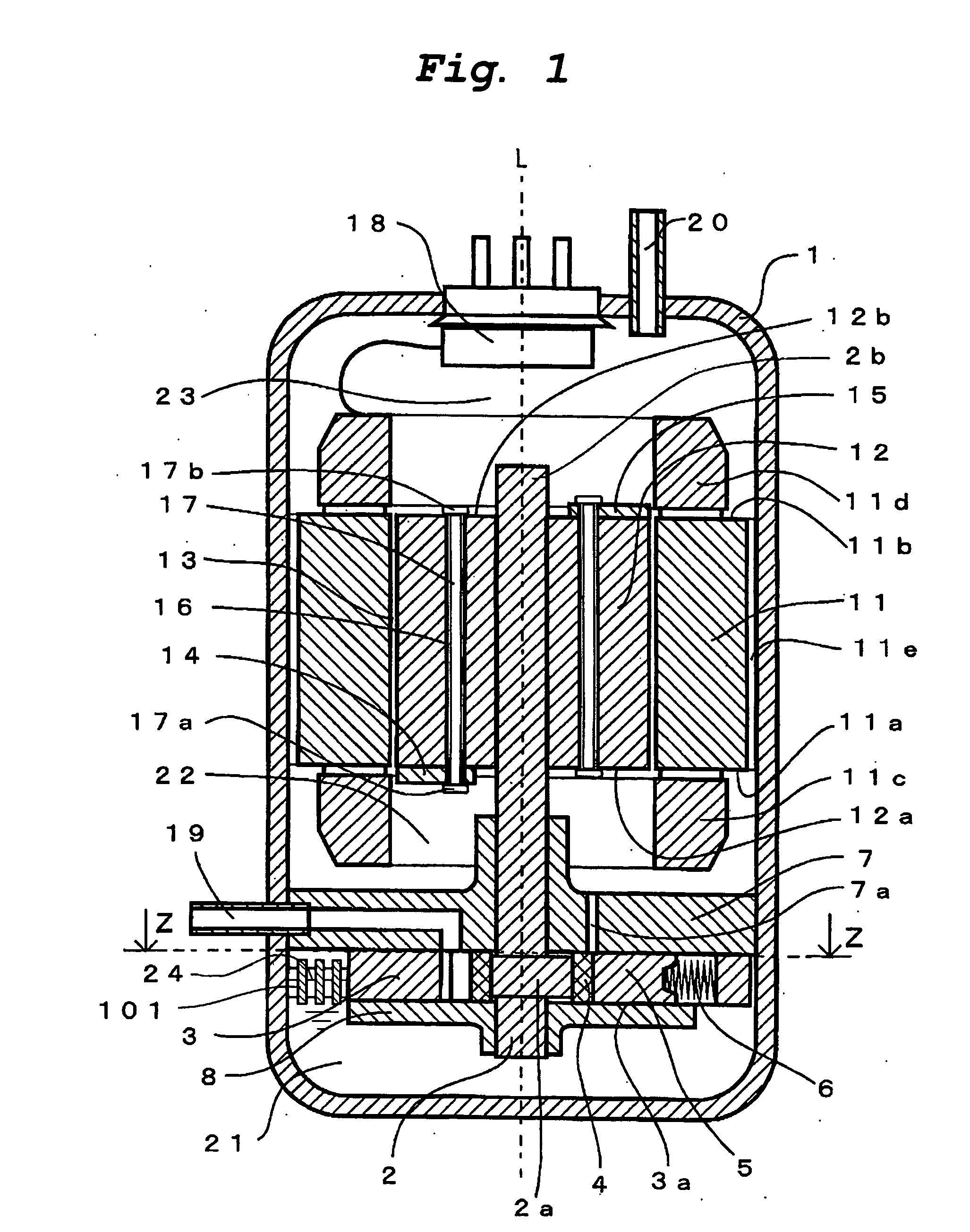
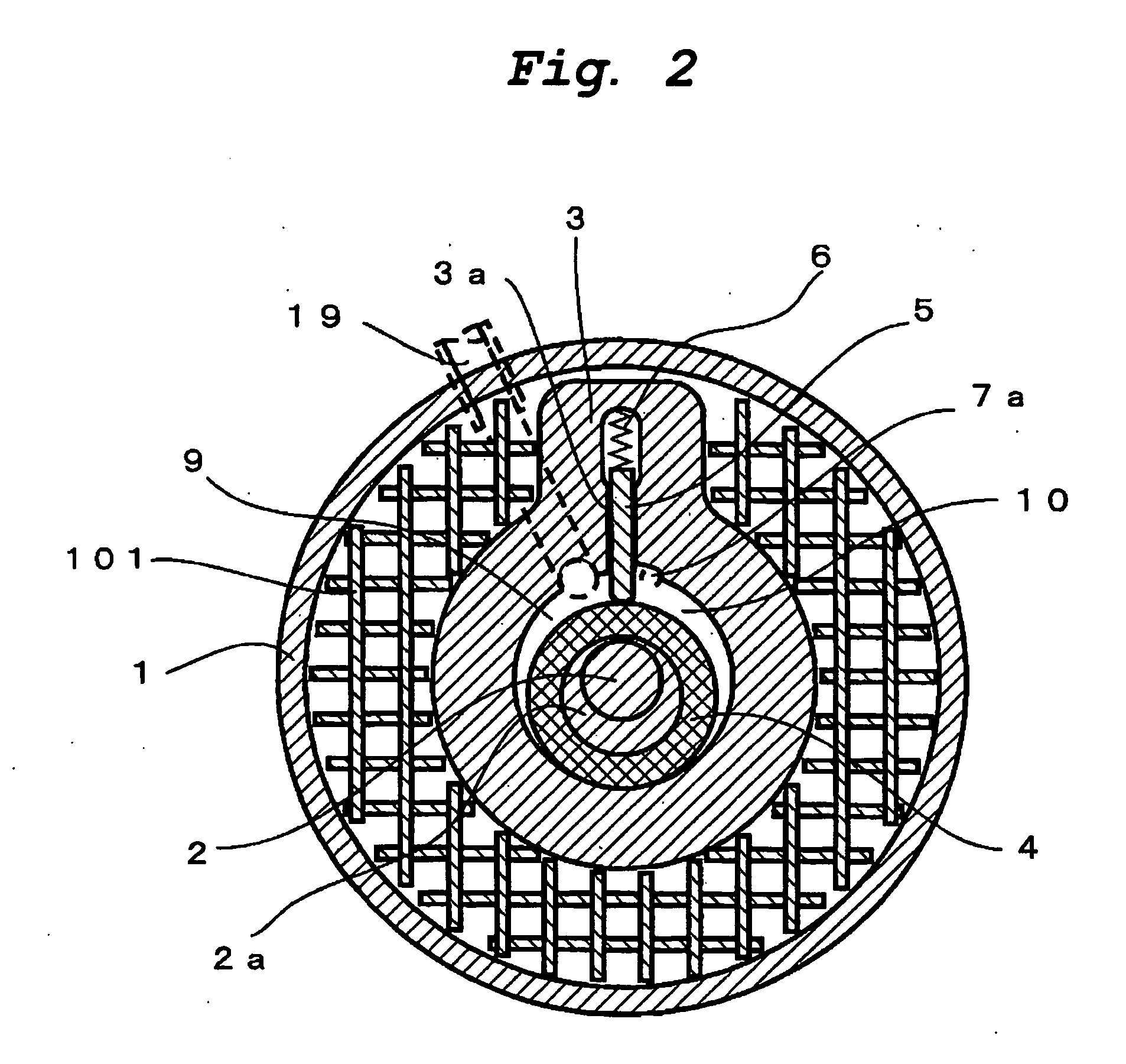
[0070] A compressor of a first embodiment of the present invention is a rotary compressor, and has substantially the same structure as that of the conventional rotary compressor explained using FIG. 11, and the same elements are designated with the same symbols. FIG. 1 is a vertical sectional view of a rotary compressor according to a first embodiment of the present invention. FIG. 2 is a transverse sectional view of the rotary compressor shown in FIG. 1 taken along the arrows Z-Z.

[0071] The rotary compressor of this embodiment includes a container 1, a compressor mechanism disposed in a lower portion of the container 1, and a motor disposed in an upper portion of the compressor mechanism.

[0072] The compressor mechanism includes a shaft 2 which has an eccentric portion 2a and which rotates around a center axis L, a cylinder 3, a roller 4 which is fitted into the eccentric portion 2a of the shaft 2 and which eccentrically rotates in the cylinder 3 when the shaft 2 rotates, a vane 5...

second embodiment

[0093] A compressor of a second embodiment of the present invention is substantially the same as the rotary compressor of the first embodiment explained with reference to FIGS. 1 and 2, and the same elements are designated with the same symbols. Explanation of the same structure and its operation will be omitted.

[0094]FIG. 3 is a vertical sectional view of an oil reservoir and its periphery of a refrigeration cycle of a second embodiment of the invention. FIG. 4 is a transverse sectional view of the rotary compressor shown in FIG. 3 taken along the arrows Z-Z.

[0095] The rotary compressor of the second embodiment is different from that of the first embodiment in that honeycomb members 102 float as the divided member in the interface 24 between the working fluid and the refrigeration oil of the oil reservoir 21, and mesh members 103 are inserted into and fixed to the plurality of vertical holes of the honeycomb members 102.

[0096] That is, the bulk densities of the honeycomb member ...

third embodiment

[0108] A compressor of a third embodiment of the present invention is substantially the same as the rotary compressors of the first and second embodiments, and the same elements are designated with the same symbols. Explanation of the same structure and its operation will be omitted.

[0109]FIG. 5 is a vertical sectional view of an oil reservoir and its periphery of a refrigeration cycle of a third embodiment of the invention. FIG. 6 is a transverse sectional view of the rotary compressor shown in FIG. 5 taken along the arrows Z-Z.

[0110] The rotary compressor of this embodiment is different from that of the first embodiment in that a porous member 104 floats as the floating type wave-suppressing members in the interface 24 between the working fluid and the refrigeration oil of the oil reservoir 21. That is, the bulk density of the porous member 104 is greater than the density of the working fluid and smaller than the density of the refrigeration oil, the porous member 104 floats ast...


PUM

PropertyMeasurementUnit
latticeaaaaaaaaaa
densityaaaaaaaaaa
sizeaaaaaaaaaa

Abstract

A plurality of vertically standing plates are assembled in a lattice form to a divided member 101 as a floating type wave-suppressing members. The divided member 101 is allowed to float in an interface 24 between working fluid and refrigeration oil of an oil reservoir 21. The interface 24 is prevented from rippling by turning flow, oil drops torn from the interface 24 by the turning flow is reduced, and oil drops of the refrigeration oil are prevented from being supplied from the interface 24 to the working fluid.

Description

[0001] With this, the floating type wave-suppressing members can follow the vertical variation at a position of the interface, and the wave-suppressing member can move to a position where the wave-suppressing member itself can exhibit the oil drops scattering-preventing effect. [0002] With this, it is possible to prevent the oil drops of the refrigeration oil from being mixed into the working fluid, and to reduce the amount of refrigeration oil to be taken out from the container, and it is possible to enhance the reliability and efficiency of the compressor and the refrigeration cycle using the compressor. INDUSTRIAL APPLICABILITY [0003] As described above, the present invention is suitably applied to a compressor having lubricant oil, i.e., refrigeration oil, and is suitable as a compressor used for refrigeration cycles such as a refrigerator-freezer, an air conditioner, a boiler, a vehicular air conditioner and the like. TECHNICAL FIELD [0004] The present invention relates to a co...

Claims


Application Information

Patent Timeline
Patent Type & Authority Applications(United States)
IPC IPC(8): C09K5/04F04C18/356F04C23/00F04C29/02
CPCF04C18/3564F04C23/008F04C29/026F04C2210/261
Inventor OKAICHI, ATSUOHASEGAWA, HIROSHINISHIWAKI, FUMITOSHI
Owner PANASONIC CORP
Learn More